


Destroying a working chairlift could be considered an affront to modern tramway technology. Old chairlifts never die, but are usually rebuilt at another location. What good could there be then in using an old chairlift to destroy itself? There would be no financial advantage as the pieces would still have to be removed.
Bill Chambers, a Winter Park lift mechanic, asked himself this question early this spring as Winter Park was preparing to remove the Estkimo Chairlift, a Riblet double that had served them well during the preceding 27 years. The lift was to be replaced and Bill, determined that it not be used again, suggested that to use the lift as a full scale fire drill would provide answers to some operational questions that have long been debated.
How could the destruction of the Estkimo lift provide useful information to aid the ski industry? This thoughtful query set minds in motion to devise a series of tests that might satisfy this question for lift designers, lift mechanics and ski area operations personnel. Along with Winter Park lift mechanics, Bill Chambers, Dan Strickland and Karl Dahle, Randy Woolwine, Winter Park’s Mountain Manager, and Jim Fletcher, President of Jenlynn International, devised the testing plan.
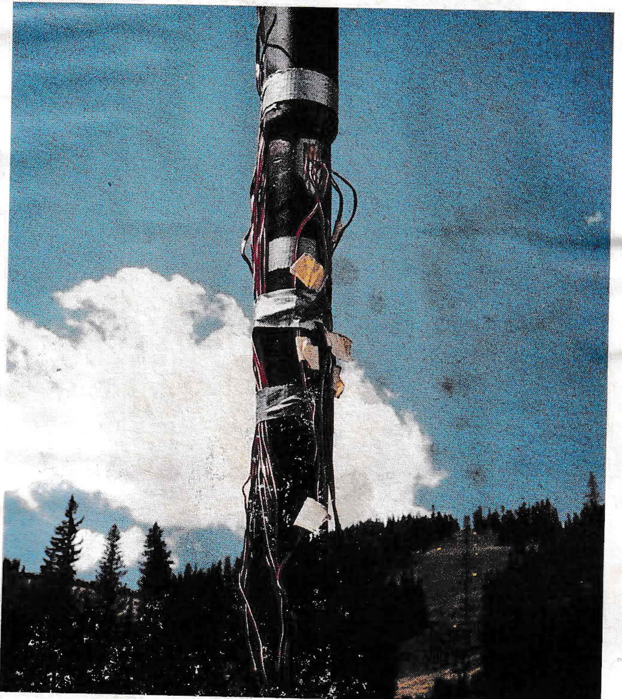
The plan included deropement testing, chairs caught in the tower structure, trees falling on the rope, brake testing without the drive shaft with the rope excessively lubricated, dynamic strain measurement on chairs, ultimate strength determination of tower foundations and the first test. The equipment was prepared and the testing began on June 18, 1990. It would be completed on the morning of the 20th, with the strain gauge measurements having been taken on the 15th.
Day One
The first set of tests to be conducted were those concerning the brakes. The service, emergency and traction rope brakes had previously been torque tested to the standard prescribed values. The chairlift was loaded with a total of 29,000 pounds of concrete discs each weighing 57 pounds placed equally on 72 of the 155 chairs. This weight represented 110 percent of the full uphill design load. Both the service and emergency brakes were applied individually with the lift traveling in the reverse direction at varying speeds up to a maximum of 550 feet per minute (fpm). The design operating speed of this chairlift was 500 fpm.
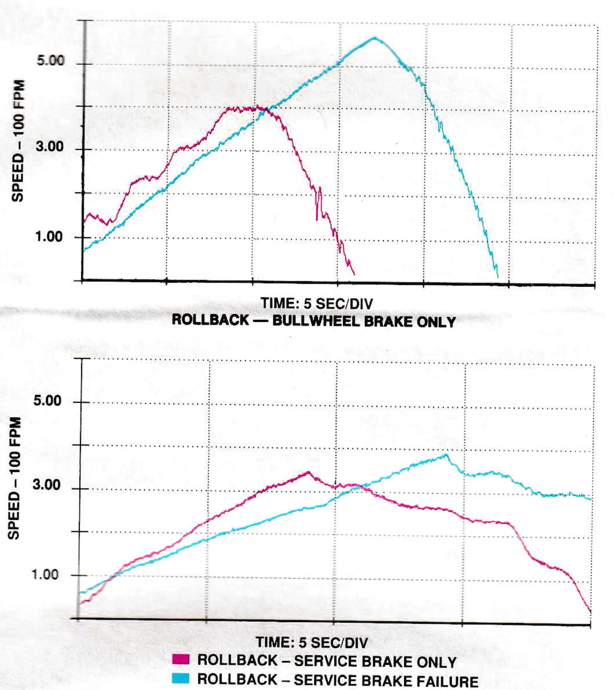
With the lift operating in reverse at 400 fpm, it failed to stop upon applying only the service brake which became inoperable due to the heat generated in the shoes. In order to stop the lift, the bullwheel brake was applied. The service brake was a shoe-type brake, applied by a spring and acting on the input shaft to the gear reducer. The bullwheel brake was a Yan 1500 acting directly on the flange of the bullwheel.
The chairlift was again operated in reverse at a maximum speed of 550 fpm with only the bullwheel brake being applied. The lift stopped adequately with a maximum deceleration rate of 1.53 ft./s2. During this test the haul rope derailed on the upgoing side at the upper terminal when a chair was lodged in the guidage. The speed vs. time curves during the stops is shown in Figure 1.
For the last test in this series, the main drive shaft connecting the gear reducer to the bullwheel was disconnected at the coupling adjacent to the gear reducer. The lift was allowed to travel in reverse with a couple of loaded chairs passing around the bullwheel. At this time it was instructed that the chairlift be stopped using the bullwheel brake. The control panel for this lift has two stop buttons. Inadvertently, the normal stop button was depressed instead of the one controlling the bullwheel brake. The lift gained momentum in the reverse direction. Later it was determined that the lift attained a maximum speed of 1500 fpm. The concrete discs became 57-pound guided missiles as they were hurled up to 120 feet from the center of the bullwheel. Chairs were dislodged from the rope and flung in all directions becoming tubular steel pretzels in the process. Observers were seen running.
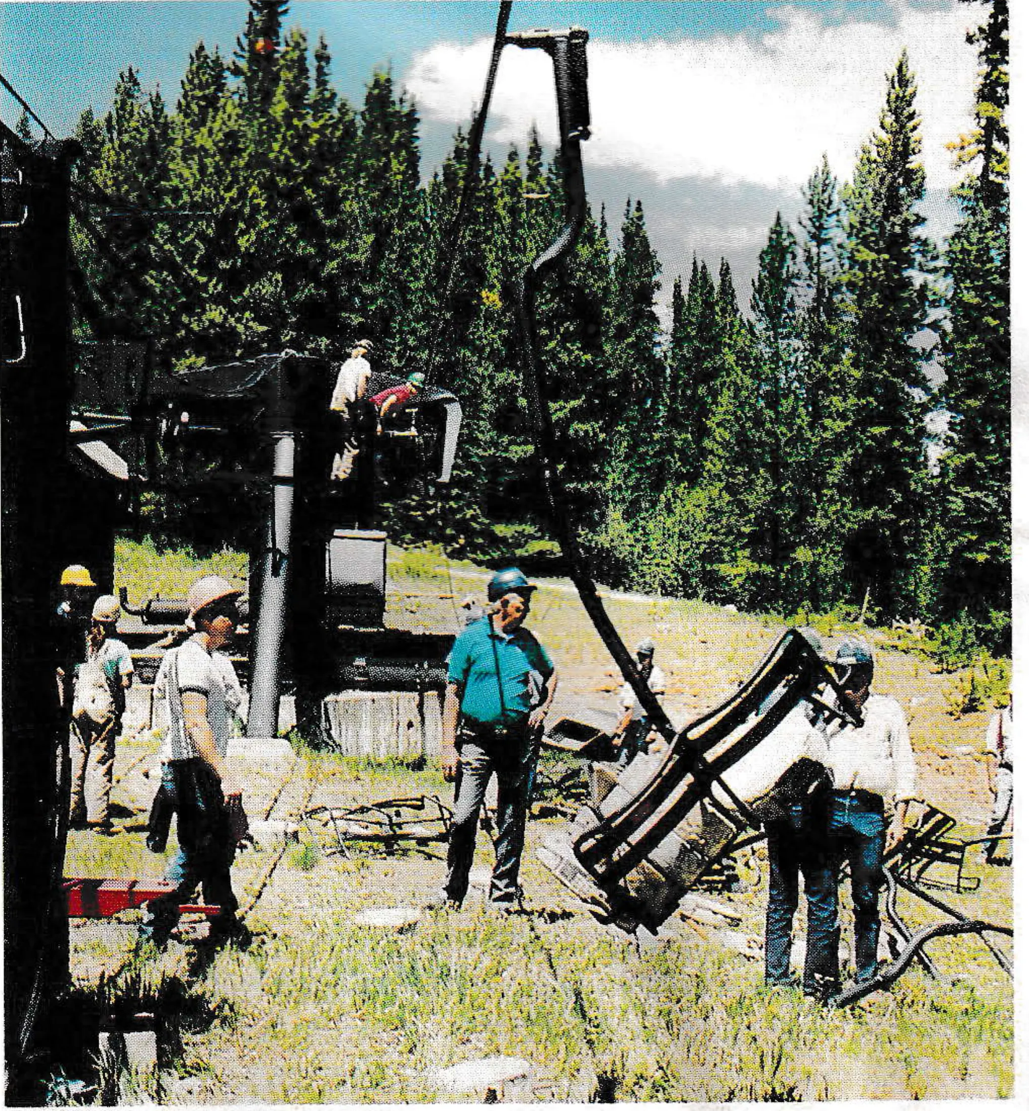
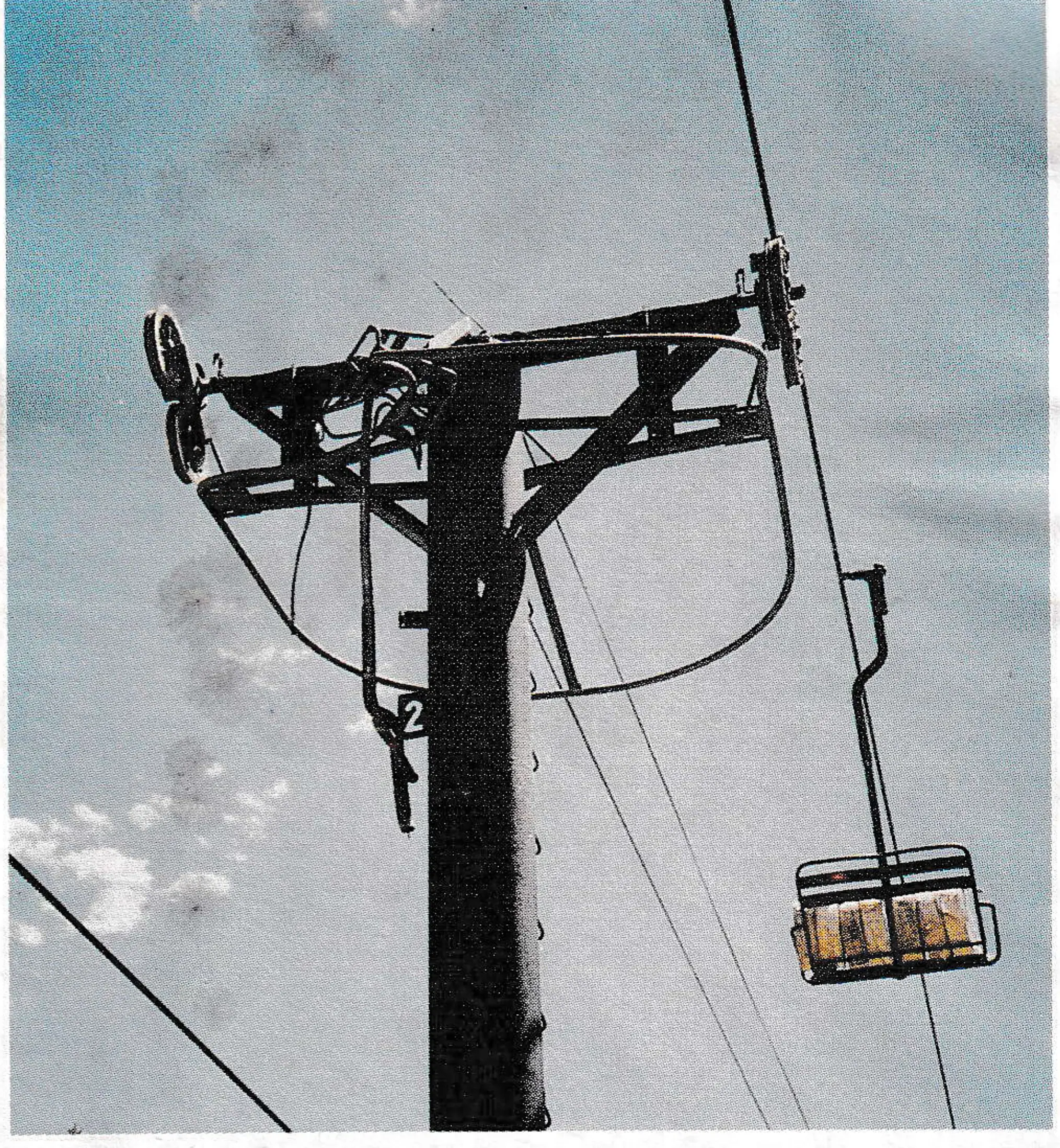
What had taken place was an uncontrolled reverse rotation with loaded chairs, observed by several technical experts and fortunately by two video cameras. The results were sobering as observers sorted through the remains not believing the results. The total distance that the chairlift traveled in reverse was 1440 feet or 24 chair lengths. Chair #74, the first empty one behind the loaded contingent, dislodged itself from the rope at tower #6, apparently when the chair stem contacted a sheave. Amazingly, no chair clips were broken, as several were transmitted through the wire rope, damaging strands in several places. One chair found itself hanging from the top center of a tower upside down. One sheave axle catastrophically failed. The terminal guidage was twisted beyond repair as chairs attempted to pass around the bullwheel in a horizontal orientation. The traction rope brake became inoperable as the rotational momentum of the chairs moved the rope to the outside of the brake. The chairlift eventually slowed and stopped due to the forces of destruction.
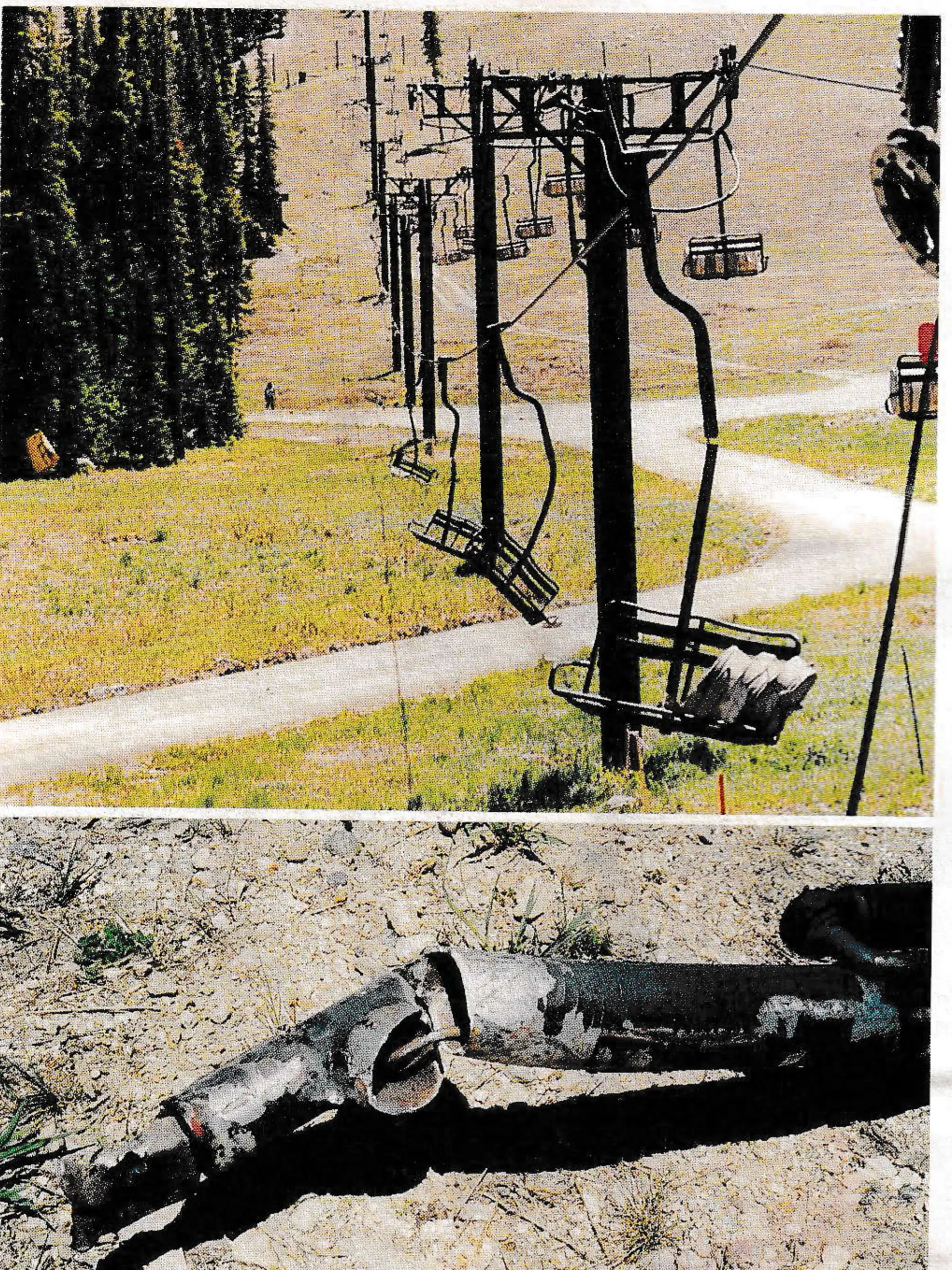
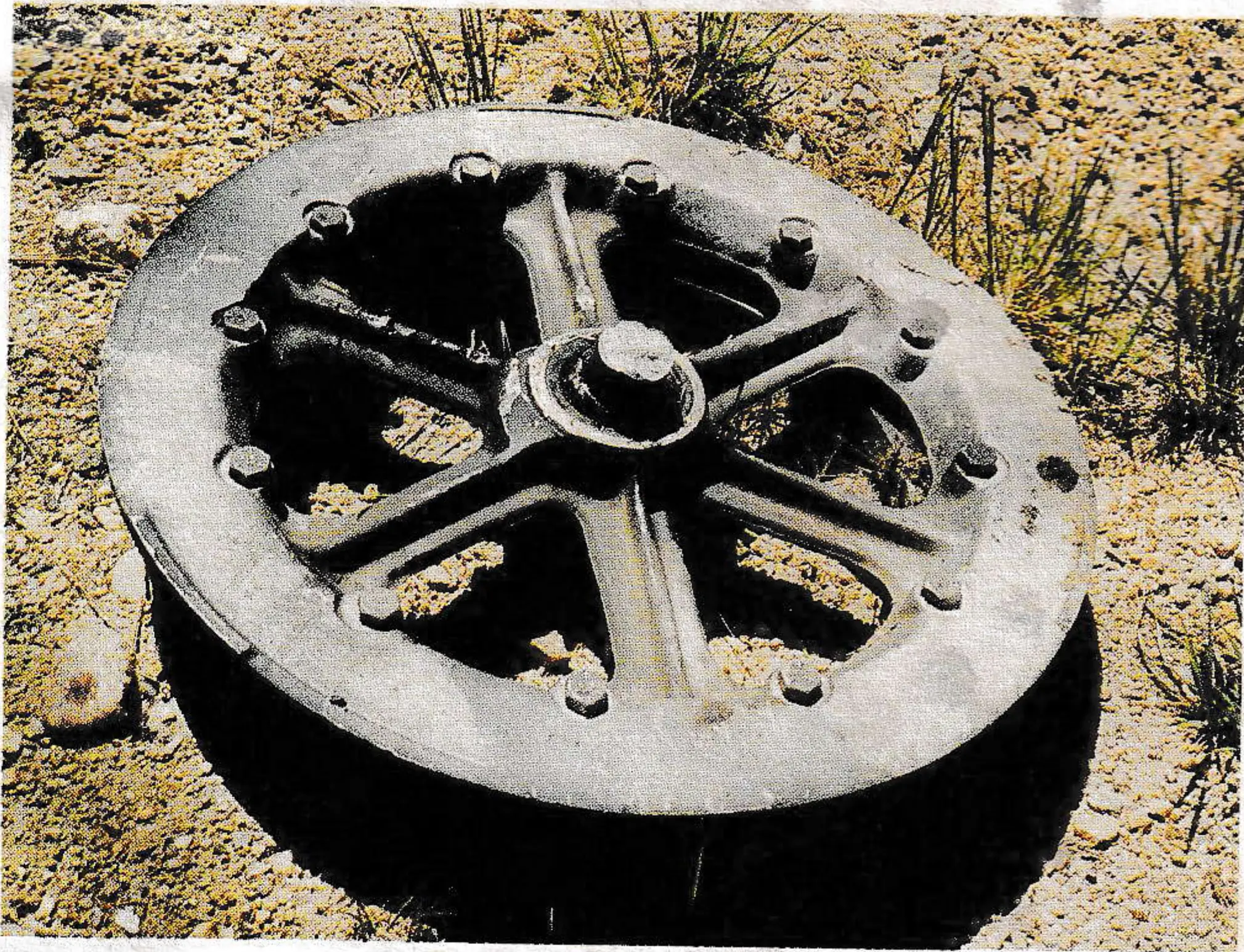
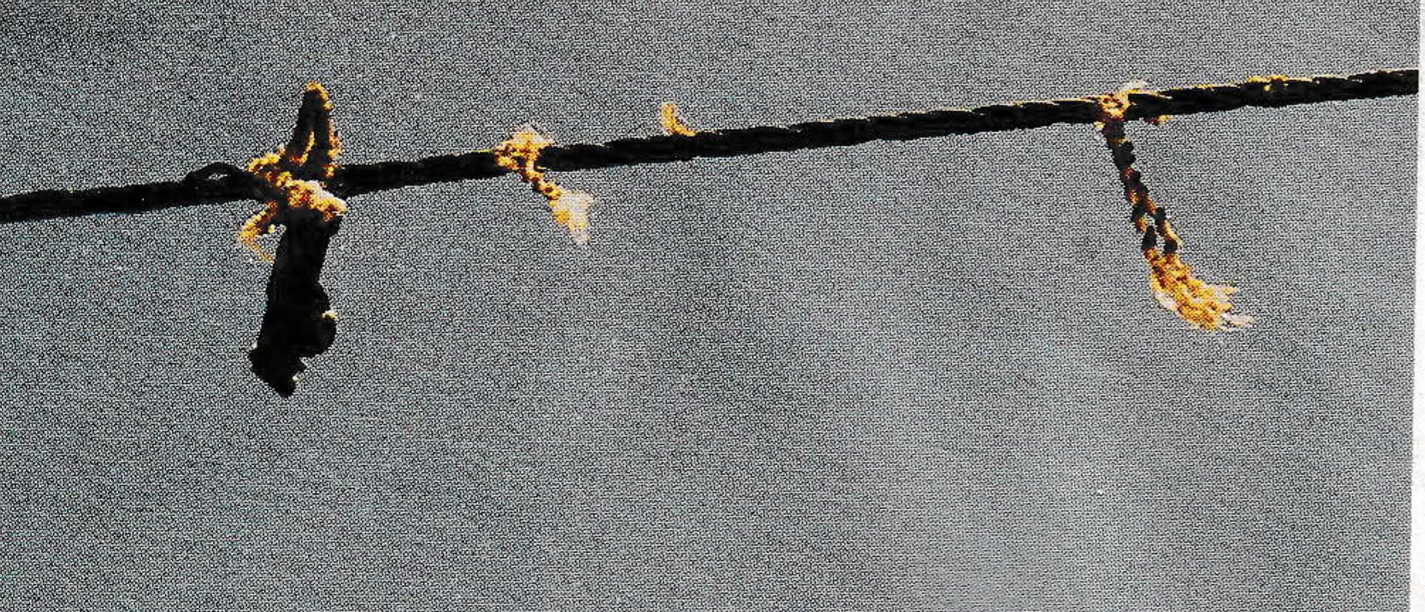
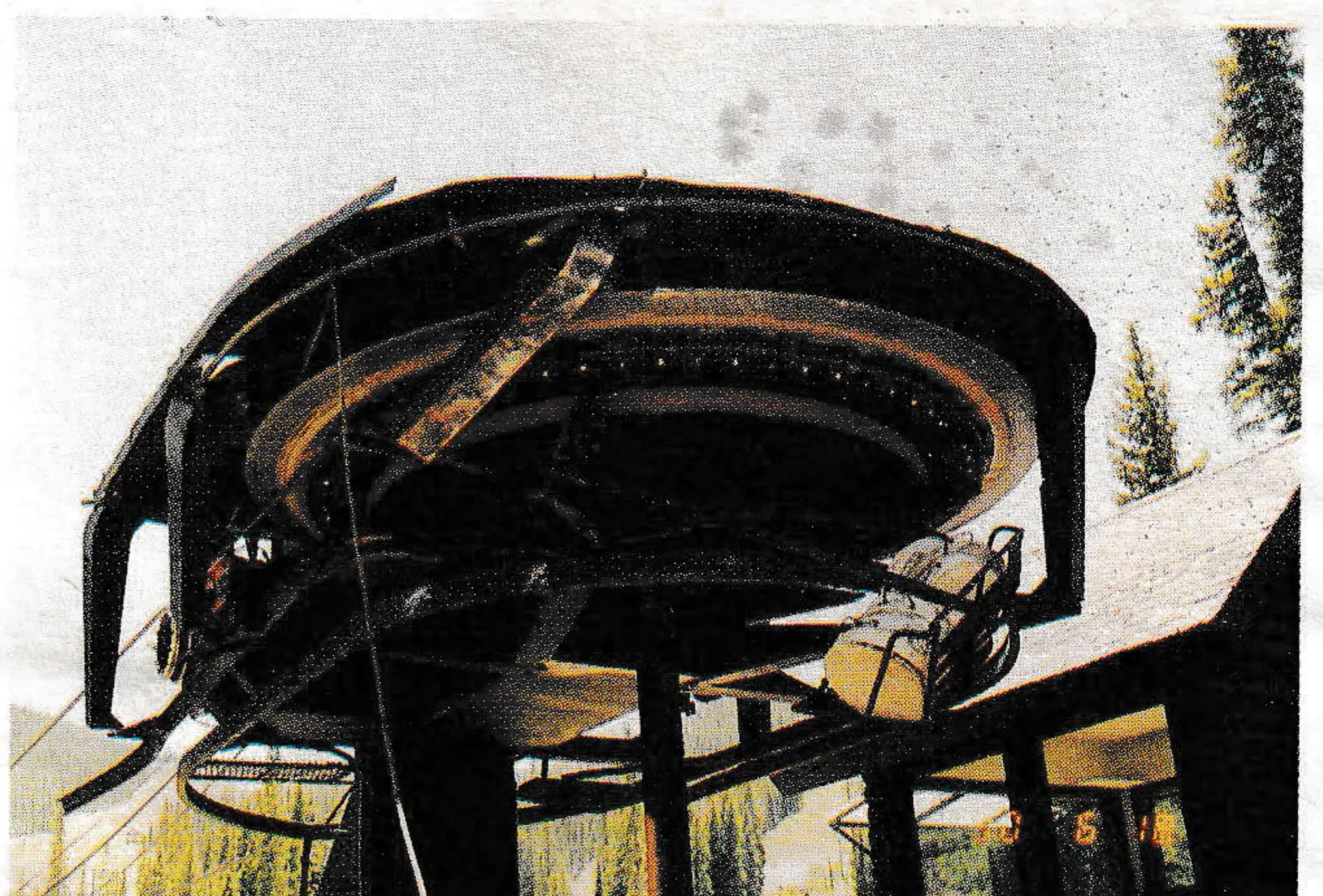
The lift was in disarray and the major question being asked was, “Would the remaining tests have to be canceled?” The Winter Park lift mechanics answered this question in the negative by working into the night. The lift would be ready to run the next day.
Day Two
As testing was resumed on June 19th, chairs 1 through 50 were loaded, with a few having less than the full number of concrete discs. There were no chairs on the line from number 51 through 72 as they had been piled for scrap. Additionally, there were no sheave assemblies on the upgoing side at towers #18 and #20.
The initial tests performed on the 19th were more brake tests, using the bullwheel brake with the rope heavily oiled. While the rope was being driven uphill, it would slip relative to the drive sheave generating considerable heat with temperatures at the bullwheel liner approaching 250 degrees F. The bullwheel brake again worked very well at speeds in reverse of 750 fpm.

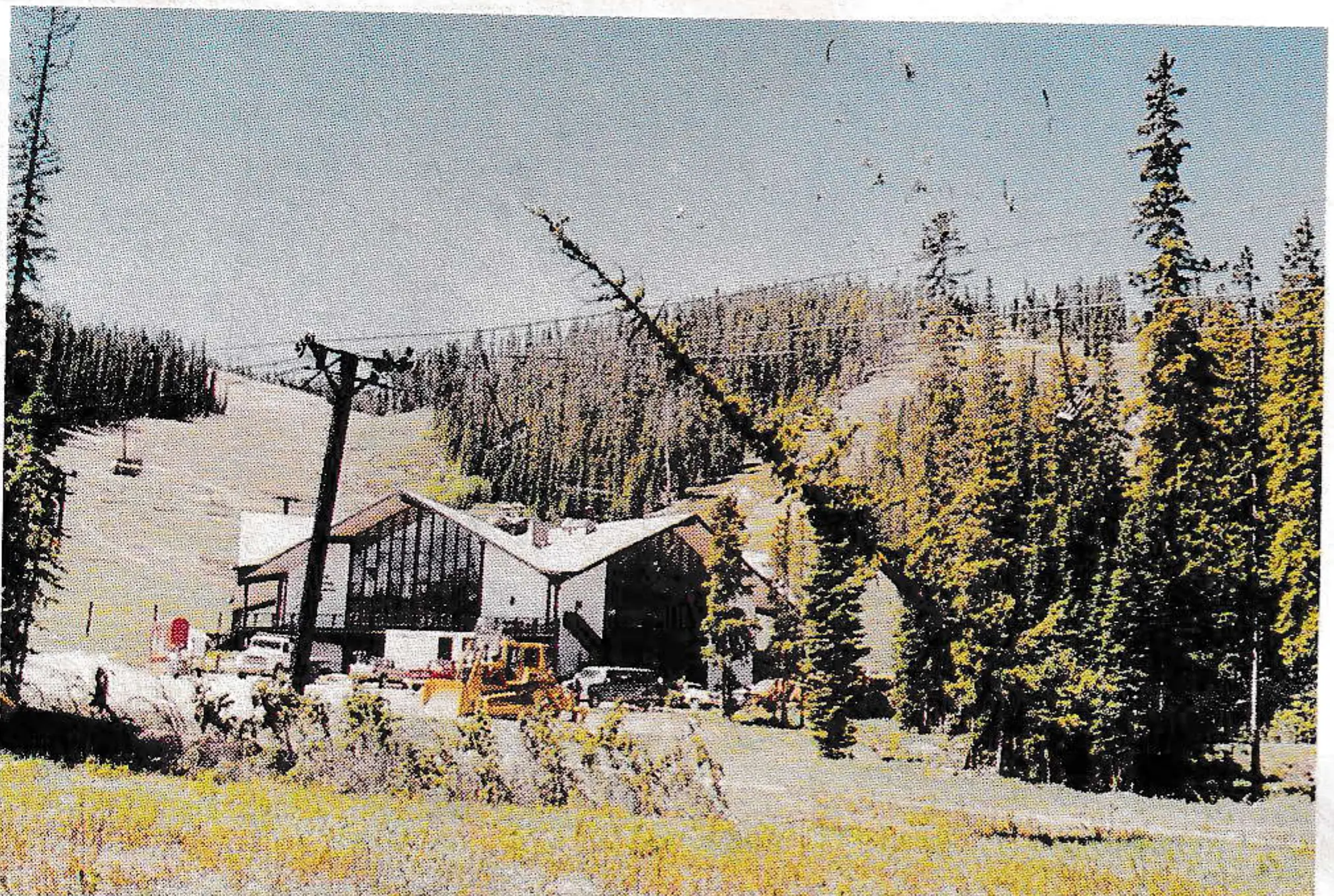
The next series of tests utilized falling trees to show the dynamic effects that are produced in a chairlift during such naturally occurring events. With the lift operating uphill, a tree 35 feet uphill from tower #4 was cut and allowed to fall on the downgoing rope. There was no carriage movement at the upper terminal; at tower #4A the haul rope was off the sheaves to the inside; and at towers #2, #3 and #4, on the downgoing side, the rope was supported in the rope catcher. Trees were also felled on the upgoing side at towers #16 and #19 with little dynamic effect.
The Fire Test
Following these tests, the most dramatic test began. The fire test, which had been the impetus for the entire testing program, was started after careful preparation, including the stationing of properly equipped professional fire fighters around the lower drive terminal. Trees and other foliage were soaked with water prior to the burn.
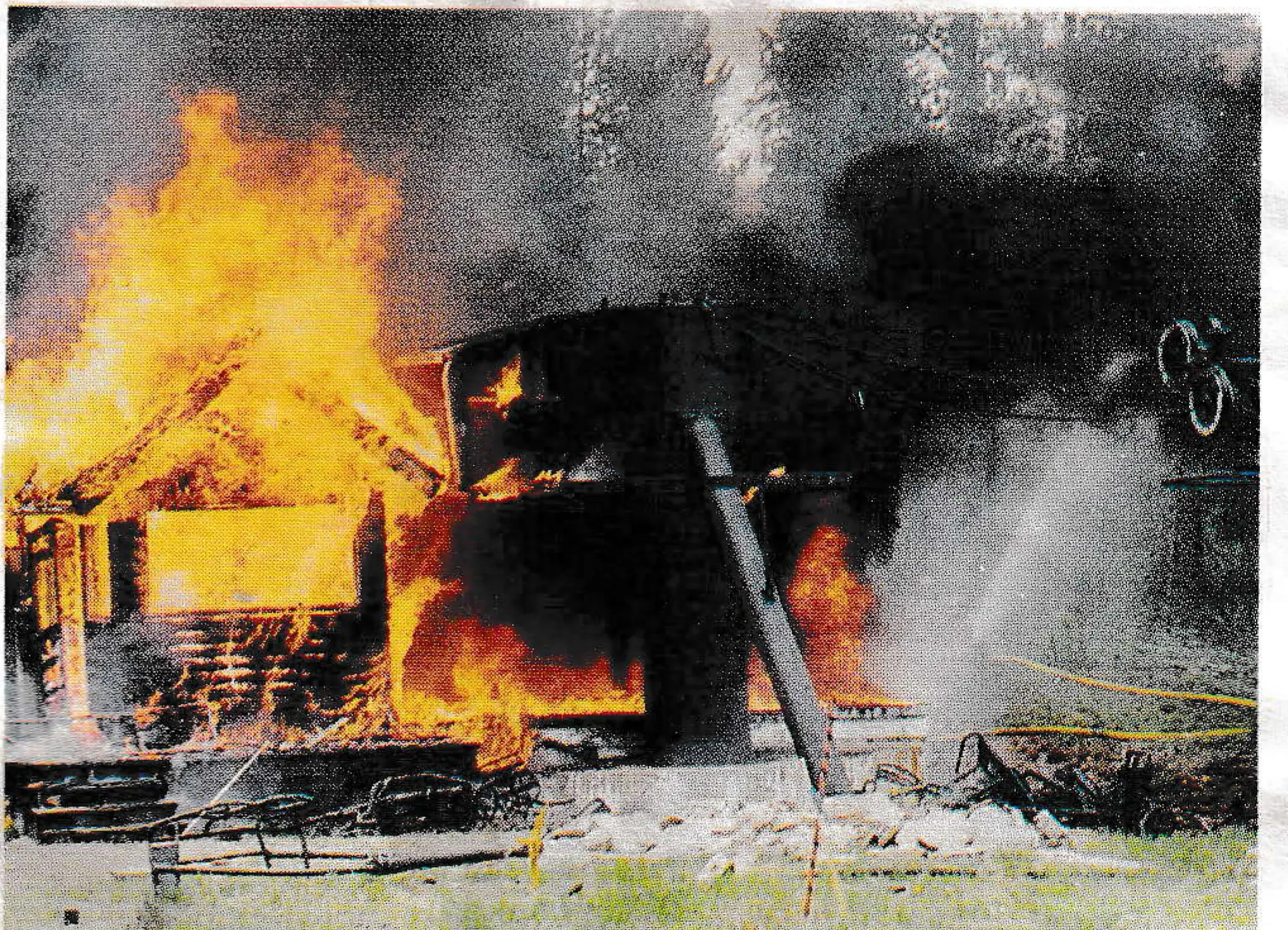
The motor room of the Eskimo chairlift was located in a concrete vault below the bullwheel. The vault had a structural wood roof covered with asphalt-based materials. The only piece of equipment that was removed from the motor room was the auxiliary power unit. The fire was started using some oily rags beneath the work bench located in the most remote corner away from the electric motor and gear reducer. The electric motor was a vertical flange mounted type setting on top of the gear reducer. After the fire was started, 27 seconds passed before the fire was evident to people in the vicinity of the lower terminal. In another one minute and eight seconds, the lift stopped from the bullwheel brake hydraulic pressure line having been severed by the heat and flames. After 14 minutes and 10 seconds from the time the fire was evident, the haul rope parted and the chairs fell to the ground. Upon examining the parted strands, a ductile failure was evident. Temperatures at the bullwheel were measured using a remote heat detection device, with a maximum temperature of 1,800 degrees F recorded six minutes and 15 seconds after the fire was evident. The temperature remained above 1,500 degrees F from the 5.5 minute mark until the 15 minute mark. The fire was extinguished by the fire fighters after 21 minutes had passed, with a temperature at the bullwheel of 1400 degrees.
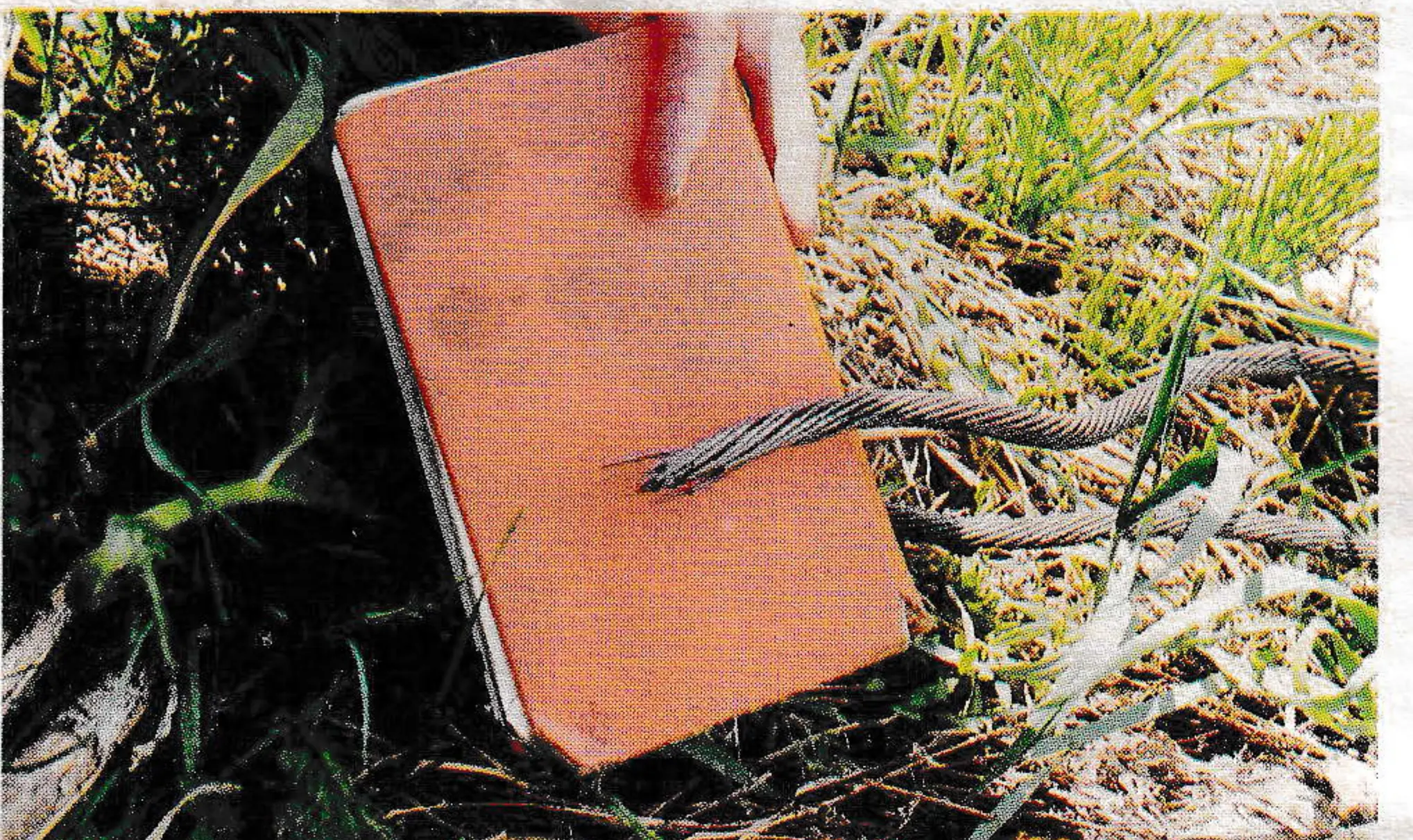
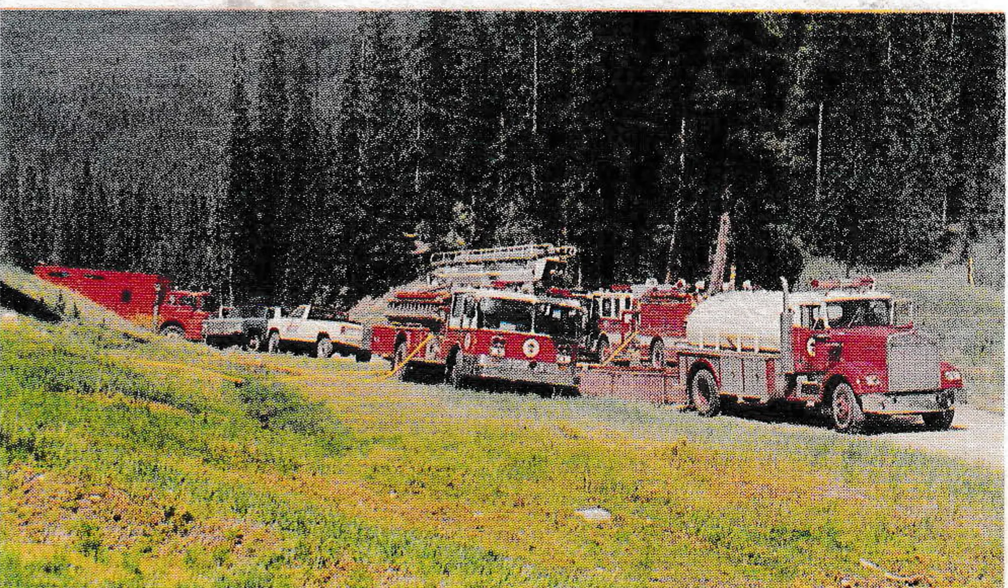
The fire test marked the end of the most exciting part of the testing program. To watch the lower terminal being consumed by fire while feeling the intense heat and seeing flames shoot out in an attempt to consume the surrounding trees, provided all of the observers with a true picture of the magnitude of such an event.
Although much less dramatic, the series of tests that followed the fire test provided a wealth of information concerning the ability of embedded concrete foundations to resist lateral loads that attempt to force them out of the ground. A total of four tower foundations were tested, two of deep block footing of Riblet Tramway design and two of Shallow block footing of Lift Engineering design. During two of the tests, forces were applied at the top of the tower perpendicular to the direction of travel and during two tests forces were applied parallel to the direction of travel. The steel tubing for the Riblet design was 18 inches in diameter with a .375 wall thickness. The Lift Engineering design was 22 inches in diameter with a .312 wall thickness. Both of the Riblet designs failed in the structural tubing, one by failure of the tube in bending and one by failure of the collar weld. Both of the Lift Engineering designs failed by uprooting the founation. The following Table summarizes the failure loads.
| TOWER NUMBER | FAILURE LOAD # | LOAD ANGLE | TOWER ANGLE | HEIGHT FT. | BASE MOMENT K-FT |
|---|---|---|---|---|---|
| *5A | 6875 | 21.8 | 2.6 | 35.2 | 228.5 |
| 5 | 14300 | 19.4 | 13.1 | 31.3 | 447.5 |
| *4A | 12106 | 14.4 | 5 | 26.75 | 323.8 |
| 4 | 19250 | 11.7 | 3 | 30 | 570.8 |
| 4 @ YIELD | 9240 | 13.3 | 2.4 | 30 | 272.2 |
*A Towers indicate shallow block footing design
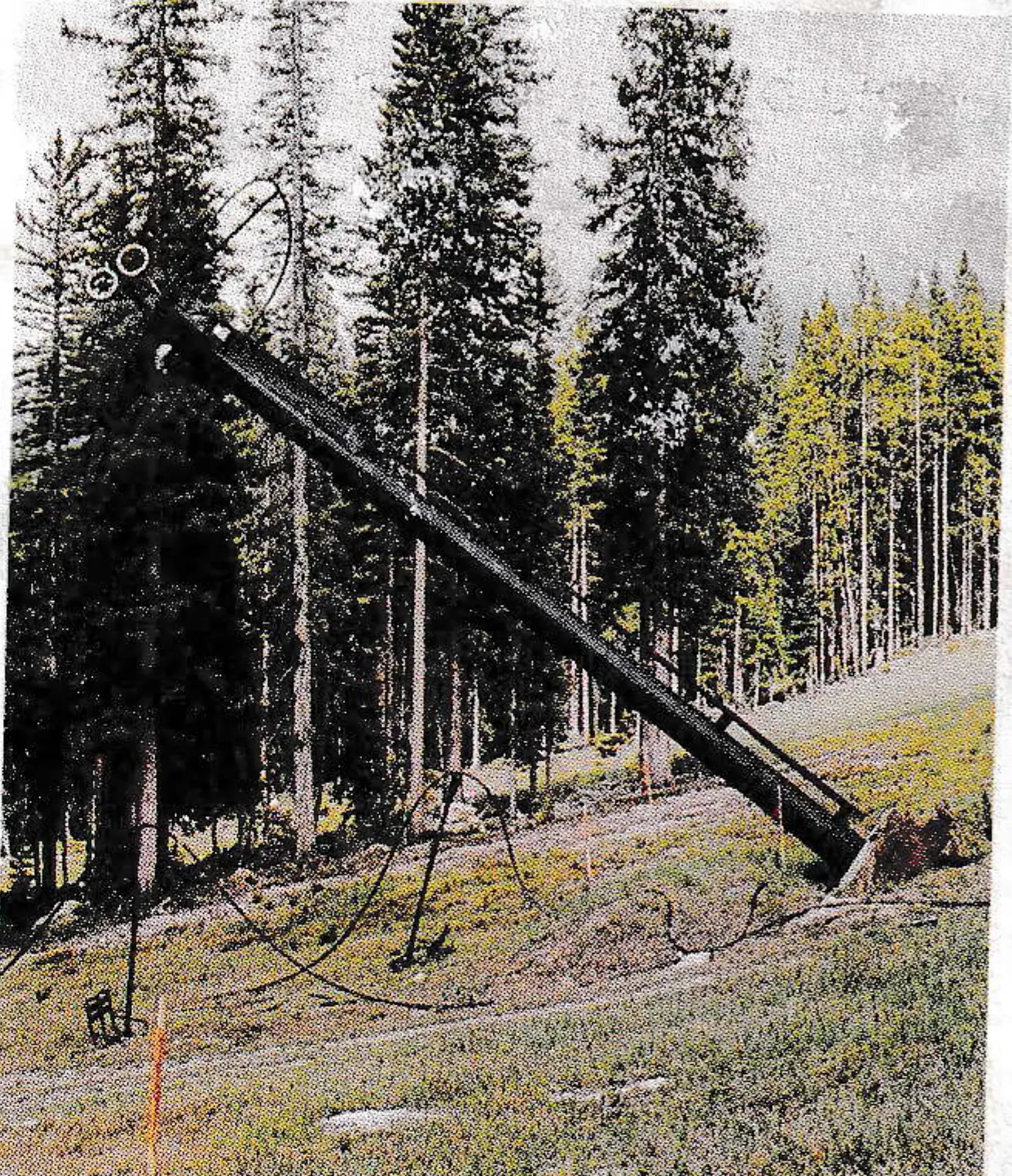
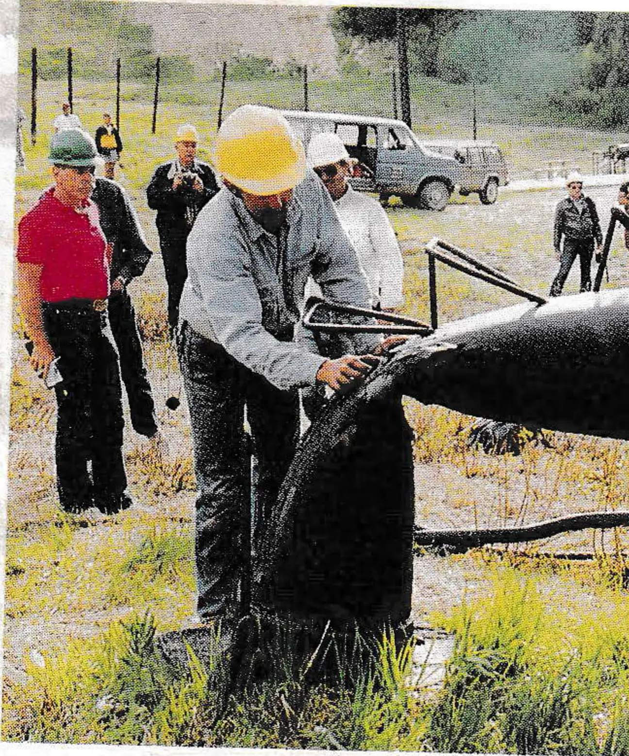
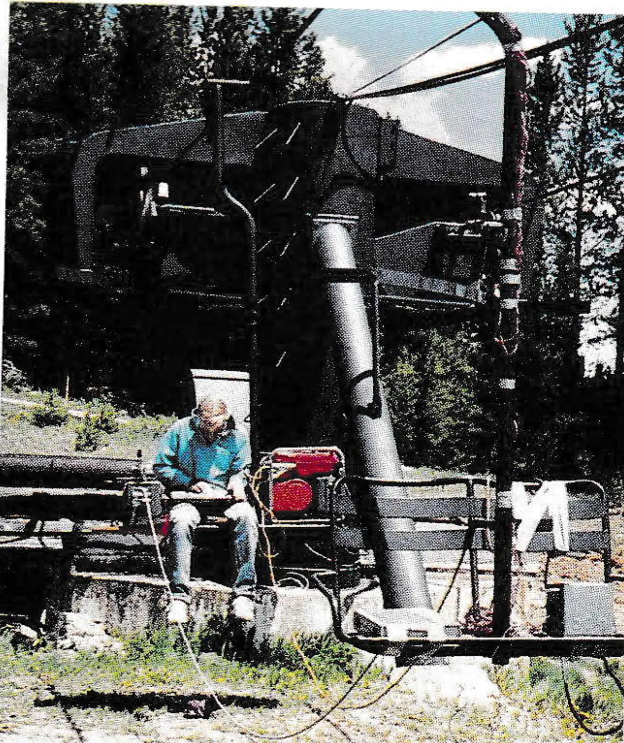
Those who assisted and attended this testing program represent a cross-section of tramway interests including manufacturers, operators, insurers, regulators and engineers. From the discussions that took place both during and after the testing, information was provided that will advance the understanding of how chairlifts perform during adverse conditions. This knowledge will enable lifts to be better designed and operated.
The contributors to this testing program include the Winter Park Recreational Association; Poma of America; Doppelmayr Inc.; Lift Engineering & Manufacturing Co.; Kendall Insurance; Pettit Morrey Insurance; Colorado Passenger Tramway Safety Board; U.S. Forest Service; OITAF; and Jenlynn International, Inc.