


The one system of a lift that can almost be counted on to give problems when lift start-up time arrives next winter is the electrical, safety, and communication system. Frequently, trouble occurs before the winter season arrives. A mid-summer inspection may reveal a relay or entire electrical panel burned out although all power to the lift had been off and no evidence of a direct lightning strike is apparent. Even lifts operated throughout the summer will occasionally become “ill” overnight. Infrequently, a lift will suffer major damage due to a direct lightning strike. Precautions and protective measures can be taken which will reduce the possibility of trouble due to electrical storms.
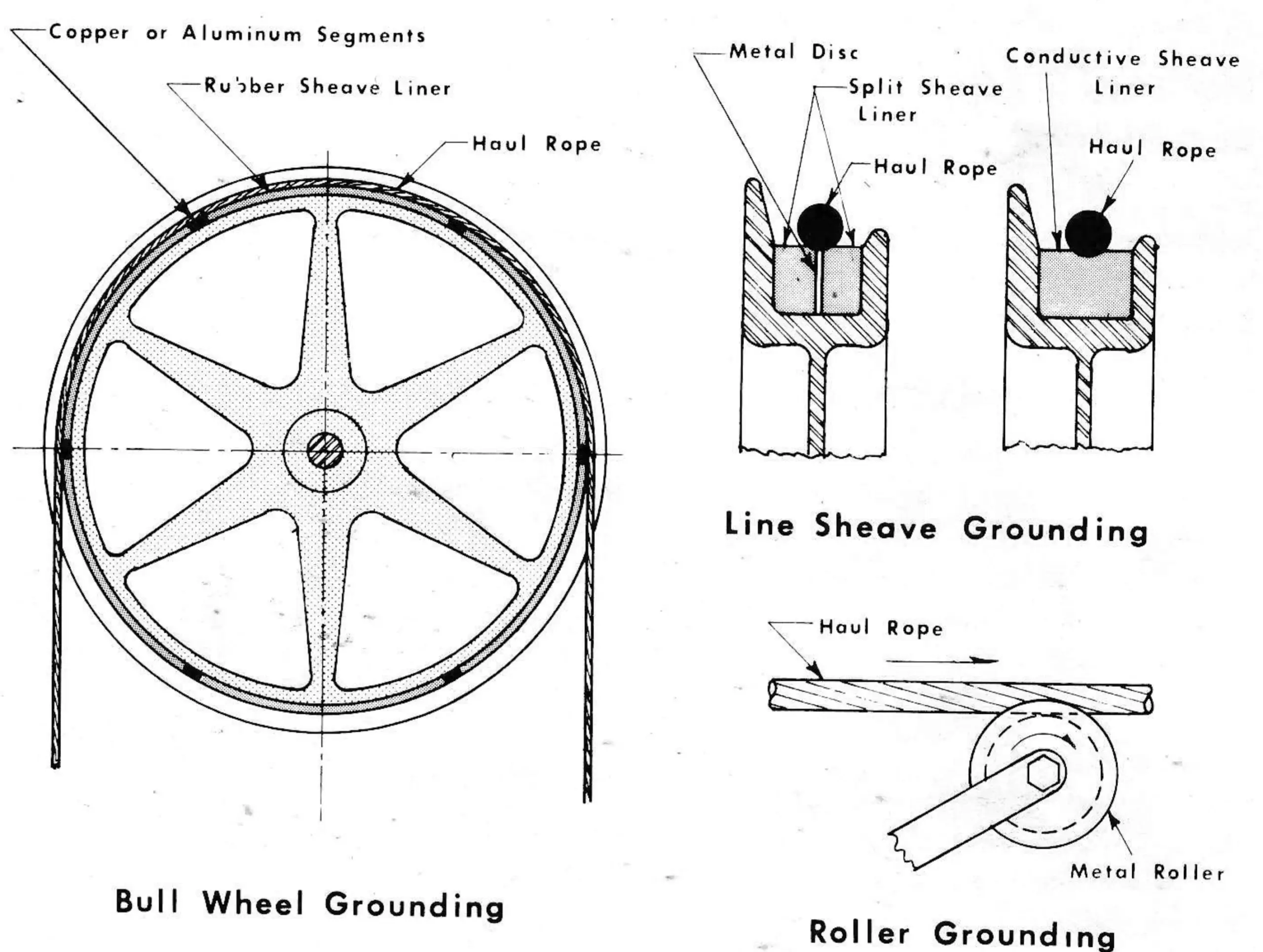
Safety standards and good practice require that certain lift parts be grounded. The newly revised ANSI Standard (B77.1-1973) adds specific requirements not previously required. What must be grounded permanently? All structures (terminals, intermediate stations, line towers, the haul rope, and electrical circuits other than low voltage safety circuits). The newly revised B77. 1-1973 Standard requires that the haul rope be grounded at all terminals and stations. Previously, grounding of the haul rope at one location was adequate. Step one in your summer program is to provide for the additional grounding of the haul rope. A variety of methods are available to accomplish this. Figure 1 shows several methods in use. Consultation with the lift designer is recommended. Normally, the grounding of the haul rope provides a path of travel for electrical current from the haul rope to a terminal or station structure. Until this path is completed to the earth, little has been accomplished.
The grounding of structures to the earth can become a major problem under certain terrain conditions. A minimum requirement of the B77.1-1970 Standard is the use of a 38 inch diameter copper coated steel grounding rod eight feet long which is connected to the structure by a conductor that is at least a No. 4 copper wire (No. 4 copper wire is about 3/16 inch diameter.) It should be emphasized that this arrangement is not the only acceptable arrangement, and in cases of ledge and rock, does not offer a satisfactory solution. How do we know if we have an acceptable ground? The only practical method is to test the ground connection. This is best done with a Megger earth tester. It is recommended that a resistance of less than 25 ohms be accepted, but the entire process of testing, evaluating, and improving the ground be placed in the hands of a knowledgeable electrician. An excellent booklet on the entire grounding problem is available from James G. Biddle Company of Plymouth Meeting, Pennsylvania 19462, and is titled “Getting Down-to-Earth.” Test equipment, methods of testing, use of multiple grounding rods, effect of rod length and diameter, and other important information is contained in this 48 page booklet. For some difficult locations, it may be necessary to use an overhead ground wire extending from terminal to terminal and grounding each tower and station along the way, with all effort to obtain an adequate earth ground expended at one terminal. Ground wires laid along the ground may be acceptable, but are subject to possible damage.
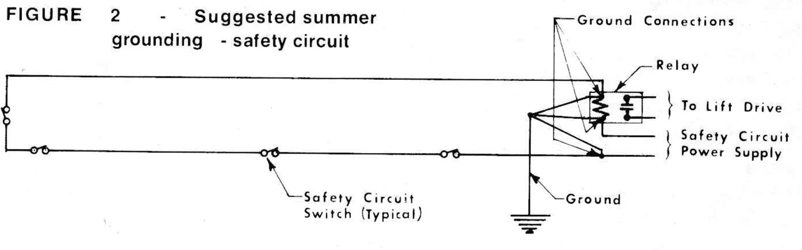
One possible source of excellent grounding for areas using snowmaking systems is the snowmaking piping