

Wire rope installation is a topic that provokes a wide range of opinions and brings about differing responses from lift manufacturers, wire rope manufacturers as well as the field installers. Opinion is split on a preferred method of wire rope installation, so the method often used is the one that is the fastest and with the least amount of installation problems. What are the long range effects after dynamic forces have had a chance to work on your new wire rope? Should an anti-twist device or “monkey tail” be attached on the lead end of the rope near the stringing splice to prevent the rope from rotating, which may add an extra day or two to the stringing process, or do we let it run around without retaining the twist?
Where does the ski industry’s “smoking finger of blame” land when things go wrong after a season of operating time has been put on an area’s new rope and they begin to experience leaning, swinging chairs, excessive chair slippage, as well as loose and breaking wires ahead of the chair grips? Who gets the blame when splice problems occur with loose and breaking wires near the tucks and in the outer wires of the strands throughout the splice area?
To better address this subject, the author sent a questionnaire to nine wire rope manufacturers and eight lift manufacturers. The survey results are presented below.
Rope Construction
The lift manufacturer must first decide on the type of rope that will be used.
There are three basic wire rope types used for chairlifts: 6×19 Seale, 6×25 Filler wire, and 6×36 Warrington-Seale (left to right above). Some minor variations from these rope constructions are also used. The 6×19 Seale ropes tend to be more stable and less susceptible to wire loosening due to the small number of large outer layer wires in the strands, but at a sacrifice of having less flexible rope which is more prone to bending stress fatigue. The 6×25 FW and the 6×36 W/S ropes have a larger number of wires bundled in the strands and have a tendency to be more sensitive to “unlaying” and “wire loosening,” but the advantage is a more flexible rope that is less prone to fatigue from bending stresses.
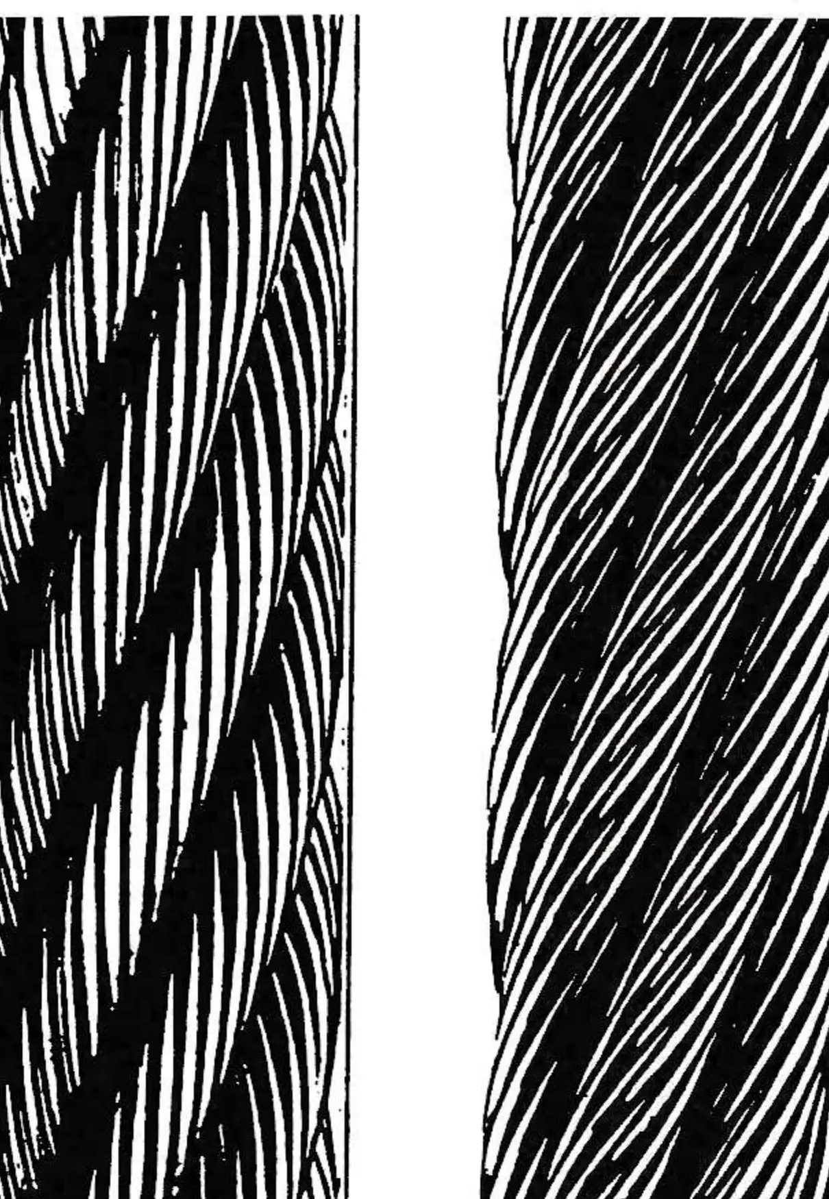
The 6×25 FW and 6×36 W/S constructed ropes must be handled with greater care to minimize altering the lay length and jeopardizing the tightness of the outer wire layer in the strand bundles. The rope construction may be either Right Regular Lay, where the strand helix is right layed and the wire helix is left layed, or Lang Lay (which is more commonly used for ski lifts), where the strand helix is right layed and the wire helix is also right layed. (See diagram.) Lang Lay has become the rope construction of choice because the wire configuration provides for a greater surface area providing resistance to external wear and giving a better gripping surface than is obtained with Regular Lay rope. It is also more resistant to internal loosening where it provides a greater wire surface area when inner strand contact occurs in the later years of rope life.
Rope Installation
When the terminals are in place and the tower machinery has been “roughed in,” rope stringing is the next step. A smaller diameter rope is pulled around which is referred to as the “sand line” or “lead line.” One end of the sand line is spliced into the new rope and the other end goes to the spooling machine that will pull the haul rope around. For larger rope diameters, splicing a stepped-up diameter sand line into the smaller diameter sand line is sometimes required. It may also be necessary on larger installations to use the chairlift’s drive to assist in pulling the rope around.
Questionnaire
1. Are you for or against retaining the rope from spinning or twisting during installation on a ski lift? Please give an explanation for your answer.
2. Should specific guidelines on the method of installation be made by the wire rope manufacturer or by the lift manufacturer?
3. How long should the lift manufacturer be responsible for the condition of the rope?
4. Do you care if excerpts from your answers are quoted and publicized with reference to your company?
Response to Questionnaire
Wire Rope Manufacturers — Nine questionnaires sent, seven responded.
1. Five were definitely for preventing the rope from twisting, two were for preventing the rope from twisting only if an apparent problem causing the rope to twist during installation became apparent.
2. Seven responded yes, with limitations to specific wire rope manufacturers’ guidelines, actual methods of installation would vary from crew to crew, equipment availability and type of installation.
3. Three wire rope manufacturers gave warranty periods varying between two seasons to five years; four responded with explanations of warranty guidelines which would depend on agreements between the lift manufacturer and the wire rope company.
4. None objected to being quoted or publicized with references to their company.
Lift Manufacturers — eight questionnaires sent; four responded.
1. Two lift manufacturers were in favor of retaining the rope from twisting; two were against retaining the rope from twisting.
2. All felt that the guidelines on the method of installation should be decided by a combination of both the lift manufacturer and the wire rope manufacturer.
3. Regarding how long the lift manufacturer should be responsible for the condition of the rope, all felt that this was up to the wire rope manufacturer.
4. None objected to being quoted or publicized with reference to their company.
Problems to Watch For
Allowing the lead end to rotate for the entire distance around the lift, results in an “unlaying” or an altering of the lay length. (One lay length equals the lengthwise distance a single strand covers in making one complete turn around the rope and is measured in a straight line parallel to the center line of the rope.)
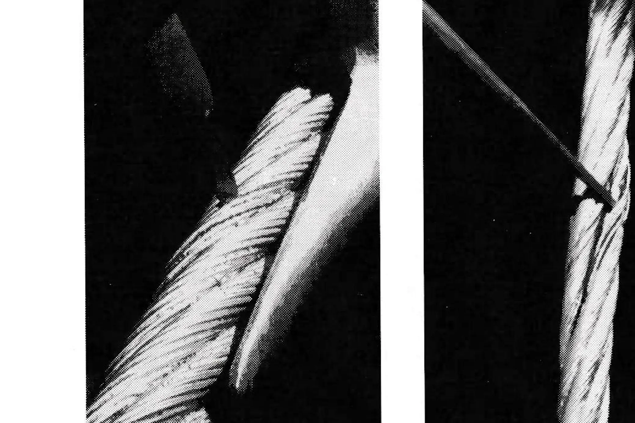
Ropes may go through significant changes during installation if proper precautions are not taken during the stringing process. Many outside influences can change the characteristics of the rope during installation. One of the most influential factors is the effect of the sand line on the haul rope during initial installation.
Sand lines are generally used many times for rope installation and have a tendency to develop accumulating twist the more times they are used. To illustrate this, when reeving blocks are used to detension/tension a rope, an anti-twist bar must be used on each block to prevent them from twisting. The reeving rope develops torque and twist when making turns around small diameter sheaves. This torque or twisting is developed similarly in such applications as a winch drum or a capstan-style spooling machine. The sand line twist is then transferred into the haul rope during reeving.

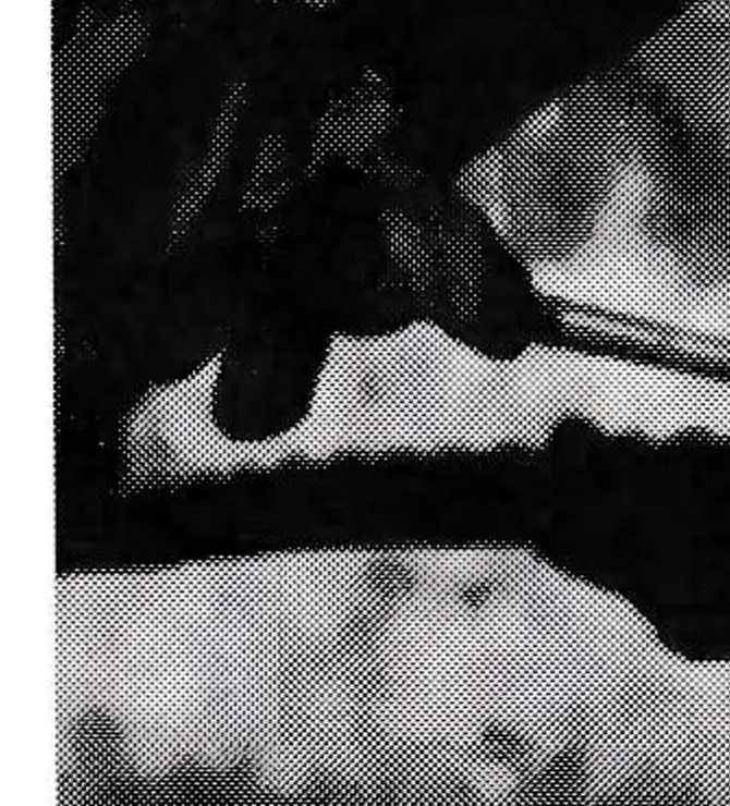
(Note: If an anti-twist device is used, it is recommended that it remain attached until after cutting the sand line from the haul rope. The majority of the torque is in the sand line, so removing the anti-twist device before making the cut will transfer the twist into the lead end of the haul rope, usually with great force. Care must be taken during this procedure because the ends sometimes spin violently after the cut has been made.)
Other factors affecting a new rope which may occur during installation are: 1) The rope may drag for a distance on the ground before reaching the first tower; 2) It may encounter some line machinery misalignment; 3) There may be a misalignment on the guide sheaves as the ropes enters the upper terminal bull wheel; and 4) There may be line gauge changes at the upper terminal which could cause the rope to roll.
All of these conditions can alter the rope’s lay length, changing the tightness of the outer wires.
The tendency of a Right Lang Lay Rope is to rotate counterclockwise when it comes in contact with an object such as a sheave, bull wheel or the ground. If you take a section of wire rope and fix one end so that it will not rotate, then rotate the free end counterclockwise as you face away from the fixed end, the strands as well as the wires in the strand become loose. To illustrate this condition, an example can be made from a splicing technique used on large diameter ropes. After a tuck has been made, a stationary clamp or vise is installed on the tuck. A second clamp is installed just past the end of the tucked tail and is used to rotate the cable one revolution counterclockwise as you face away from the fixed clamp. This loosens the strands, enabling the splicer to more easily lay the tucked tail into place. In observing the strands in the “unlayed” condition, the wires in the strands also become loose. After the clamp is returned to normal, the wires and strands immediately tighten up.
In the case of stringing a new rope, the fixed clamp would be the spool, the counterclockwise rotation can be characterized by the unretained rope end going up the hill. Without retaining the free end, if one of the outside influences causes the rope to rotate, a similar condition will occur. After the unretained rope has made the first trip around, the lead end will now have a very long lay length with loose outer wires. The other end will have a normal lay length or even a tight, short lay length. Matching the lead end of rope to the trailing end of the rope that is still on the spool where the lay length has remained the same or has become shorter is a difficult task for the splicer.
Rope twist will also occur when a new rope is being installed on an older lift using the old rope to pull the new rope around. If the old rope has twist locked in it, the twist will be transferred to the new rope making an anti-twist device a necessity.
If 200 twists are induced into an unretained rope during installation due to one or all of the previously mentioned outside influences, the rope will have 200 twists locked in for the rest of its life.
The standard method generally used for installing chairs on a new rope begins with chair #1 being installed at the lead end of the splice (usually near tuck #1) and ending with the last chair near the trailing end of the splice. On a rope where twisting has occurred, this method of installing chairs can cause the twist to be concentrated in the splice area, eventually leading to splice problems.
To illustrate this point, a ski area installed a new lift and installed the rope without using an anti-twist device. Midway through the season the chairs began to lean and the grips began to slip on the rope. At the end of the season, loose wires were observed immediately ahead of approximately 40 percent of the chair grips. The problem was severe enough that the rope needed to be replaced. The original rope was used to pull the second rope around by splicing the two together, but again, no anti-twist device was used. A one-inch wide mark was painted on the total length of the replacement rope at the time of production in order to monitor rope twist during installation. After the rope was installed, the paint mark spiraled approximately 200 times in forty foot increments. Midway through the next operating season, leaning chairs and grip slippage had resumed.
Problems of an unlayed rope will occur during the life of the rope and will not become evident until after some cycle time, and are generally concentrated in the splice area. Loose wires in the strands (usually more prominent in the trailing tucked tails in relation to the rope direction of travel) will continue to crop up throughout the rope’s life long after the manufacturer has gone. Loosening of the outer wires will not become apparent until the rope has cycled for a time — usually one season. This gives the strands in the rope time to interact with the sheaves, bullwheels and the core of the rope. The first signs of a problem can be seen immediately ahead of the chair grips where loose and arching wires surface. Leaning chairs and excessive chair slippage also point to a rope twist problem.
Why, then, is retaining the rope during installation opposed?
Some of the reasons against retaining the rope by various lift installers and manufacturers are: 1) It takes too much time; 2) It is too hard to carry a chair uphill from the spool location to a point where it can be attached so that it will clear the ground, and similarly, taken off after it has made the trip around; 3) The chair becomes snagged in sections where there is a long span and cable slack brings the chair and rope too low to the ground; 4) High spans make reaching an anti-rotation device impossible; 5) In the case of detachable lifts, the chair has to be removed upon entering the upper terminal, then re-attached on the other side; 6) If the alignment is perfect, there will be no need to retain the rope; and 7) The ever-increasing diameter of ropes for the larger installations prohibit the use of an anti-twist device.
Conclusion
The ski area purchasing the rope, the lift installer or company installing the rope, as well as the wire rope manufacturer must all work together to insure the proper care of the wire rope to insure its longest, problem-free life.
The following are suggestions on guidelines for rope installation that may help extend the life of the wire rope and help prevent long range wire rope related problems.
1. The ski area purchasing the rope and the lift must take a greater role to insure that the guidelines set by the wire rope manufacturer are followed.
2. The wire rope manufacturer must insist on proper care and handling of their product with clear guidelines on handling their product.
3. The lift manufacturer or installer must accept all liability if they decide to deviate from the guidelines set by the manufacturer.
4. If the installation guidelines set by the wire rope manufacturer are followed and problems in the rope do occur, the wire rope manufacturer must take full responsibility for their product.
This article is based on my experience of handling wire rope and tracking the history of many ropes over a period of time. I encourage concurring and opposing opinions to the theme of this paper; after all, productive, interactive exchanges of ideas is how we all further our knowledge.