


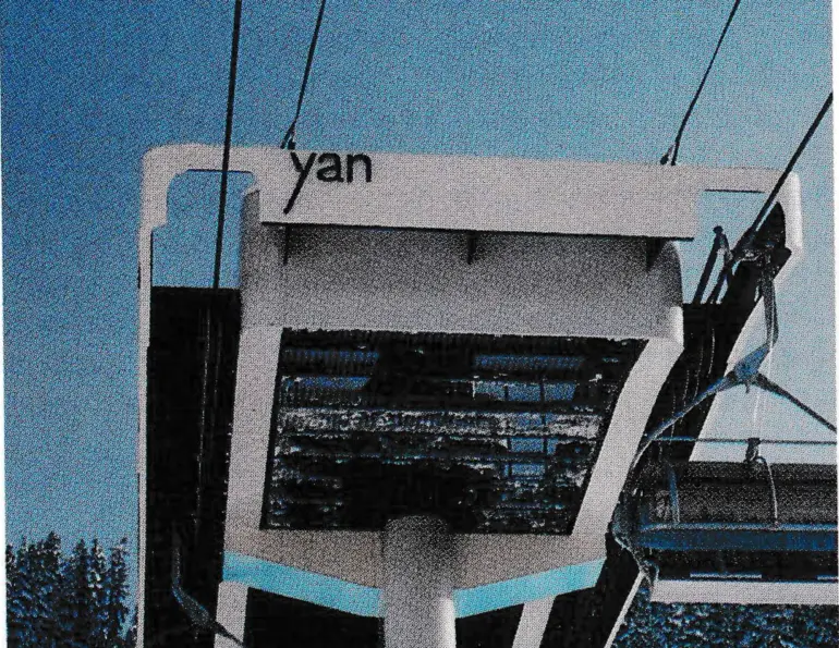
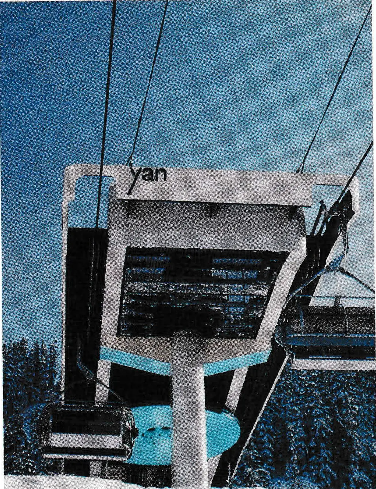
Whistler Mountain, B.C., effected a major overhaul of its lift system this year, replacing an old four-passenger gondola and three double chairs with two high-speed detachable quads. The arithmetic is compelling: practical transit time to the top of the mountain dropped from 45 minutes to 16; VTFH went from 5,400 to over 10,715; direct access capacity was increased from 700/hr. to 2,650; and the number of employees needed to operate the facilities dropped from 36 to 12.
Particular care was taken in preparation of the lift profile, which traverses many cliffs, creeks and ridges. Almost $200,000 was spent in blasting and bulldozing to bring the liftline below the tree line in the very windy access to the alpine area — money well spent in the light of early season experience.
Whistler called for full redundancy of the drive system, so each lift was equipped with dual electric motors, each capable of developing continuous torque of 4,000 foot-pounds at 950 RPM and 5,000 foot-pounds for intermediate duty.
The main gearbox, a YAN 3000, is capable of delivering 6 million inch-pounds torque, and consists of a two-stage, fully enclosed reducer. The first stage is a spur gear ring with two pinions located at 180°, and the second stage is a planetary transmission. Additionally, each drive unit has been equipped with a hydrostatic auxiliary powered by 300 HP Cummins diesels.
The electrical system consists of Lift Engineering’s 3+ control system, which includes three microprocessors, VGA color graphics and data logging. The DC drive system is a Sabina and incorporates two regenerative drives set in a load-sharing scheme, with either drive capable of full-load operations if needed. In the event of a power failure, the entire system is backed up by a 1,200 KVA Cummins/Onan generator set with fully automated switching. The diesel generators are located in a vaulted compartment together with the switching gear. The dual electric drives are in the back of the main operator house.
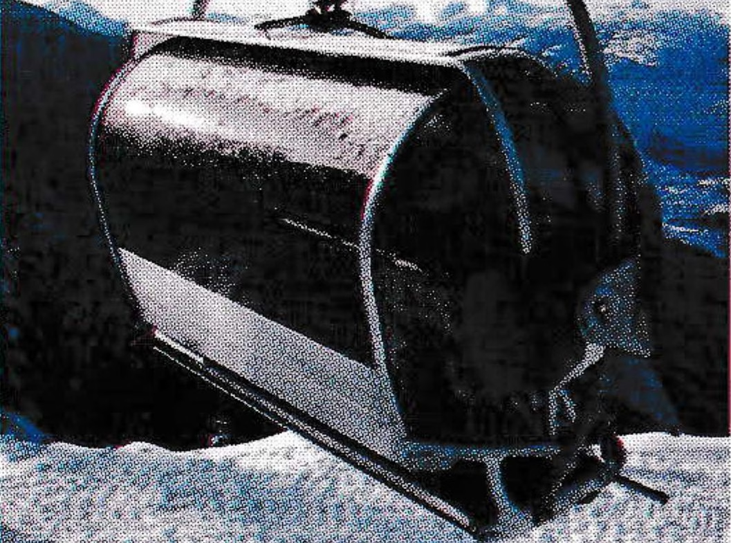
Of the new technology involved, perhaps the most interesting is in the chair seat design and new geometry of the bubble.
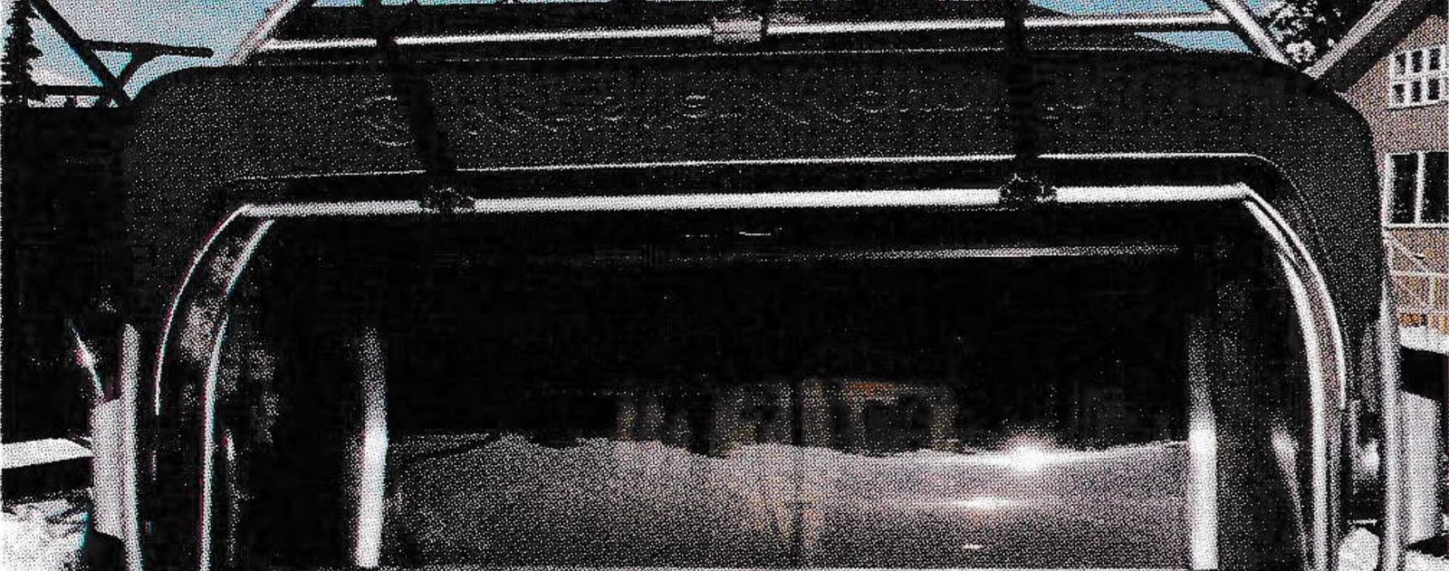
The bubble itself, which is slightly larger than others on the market, consists of two sub-assemblies. The back assembly is rigidly attached to the backrest and armrest. The pivoting front bubble and canopy is attached to the bail through independent torsion springboxes. The axis of rotation for the movable bubble section and footrest has been moved from the traditional back-of-the-seat, to chin height and a more central location.
Splitting the enclosure in the vertical plane allows for creation of a large air gap on top of the bubble, for better ventilation and reduced fogging of the enclosure. When open, the movable section rests behind the fixed section, reducing the lateral surface of the open bubble by almost 30 percent, which in turn saves terminal space and reduces wind resistance.

The torsional springboxes provide a positive upward force for the footrest, which pivots independently from the bubble. The weight effect of the movable front section of the bubble is almost entirely offset by the torsion springs. The bubble opening mechanism consists of frictional rollers powered by the movement of the carrier. This frictional drive will certainly undergo particularly hard field testing on the Quicksilver installation, which crosses at least two climactic zones and is subject to heavy icing.
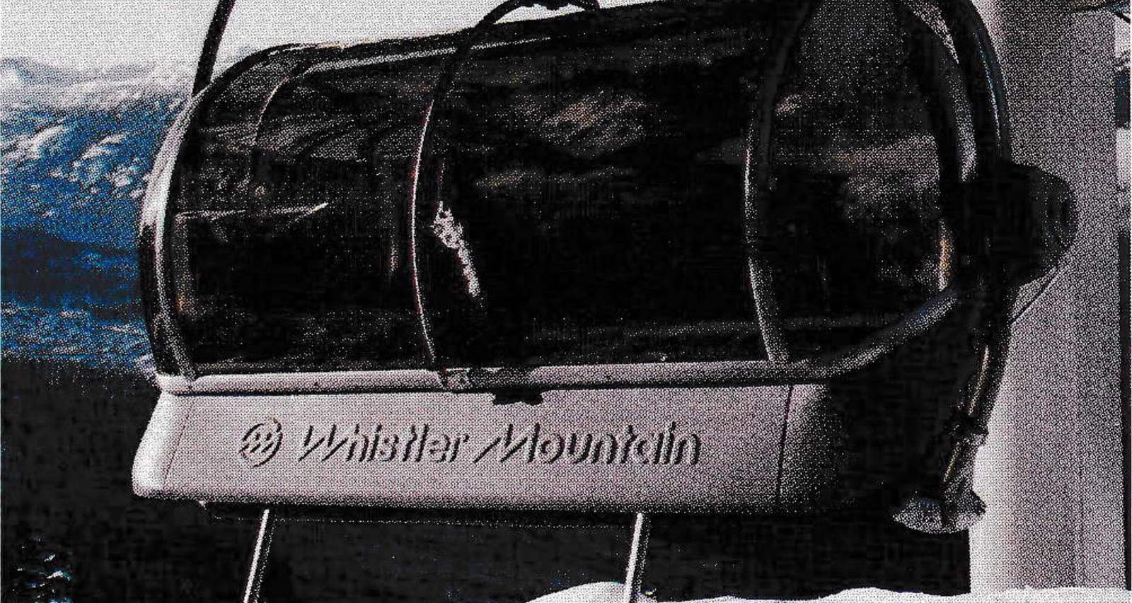
An important feature of this design is that the opening force is applied on a large radius, automatically reducing the magnitude of the force. The structural frame supporting 3/16 inch thick tinted polycarbonate by Cyro Industries and the 1/8 inch Kaydex canopy, is welded from custom-made high-strength extruded aluminum profiles.
Both bubbles consist of left and right pre-formed semi-spherical elements, and flat sheets bent into semi-cylinders. This arrangement provides enhanced optical quality in the largest transparent surface, and significant economy when considering potential replacement and maintenance of the bubbles. Since the bubble cross section is largest on the top, an overhanging effect is created, leaving the bubble surface free from snow at approximately eye level — a small but important convenience.
The chair seat and backrest are constructed from extruded aluminum panels, clamped between cast steel armrests with integrated slide-on soft fabric/foam seat and backrest padding. This design provides an extremely rigid and quiet structure, as well as a vastly improved bottom-of-the seat appearance, as seen by skiers standing on the slopes.
The wind drag coefficient was reduced by almost 40 percent in comparison with the conventional “bucket” design. This can be attributed to both the wing-like cross section of the seat and introduction of the air relief gap between chair seat/arm rest/ back rest and back bubble.
Design study for the seat and bubble started in the winter of 1990, but only in May 1991, following inspection of all other systems presently available in Europe, was the final decision made to install the new and entirely American-made bubble. It left little time and less margin for error. There were smiles and quiet pride when the lifts started running in late November. Appreciative of the strains this push had put on the L/E crew, Whistler’s Jamie Tatterfield sent the following FAX to Carson City: “Yesterday we opened and had a successful day. On behalf of all the crew at Whistler, congratulations to the L/E crew on a high quality product you can be proud of.”
| Lift Name | Quicksilver | Redline |
|---|---|---|
| Slope Length, meters | 2,051 (6,729′) | 2,494 (8,183′) |
| Vertical Rise, meters | 647 (2,123′) | 554 (1,818′) |
| Lift Capacity, uploading, people/hour | 2,650 | 2,800 |
| Lift Capacity, downloading, people/hour | 2,650 | 1,400 |
| VTFH | 5,625 | 5,090 |
| Rope Speed, meters/second | 5.0 (985 fpm) | 5.0 (985 fpm) |
| Loading Interval, seconds | 5.4 | 5.1 |
| Carrier Spacing, meters | 27.15 (89.1′) | 25.7 (84.3′) |
| Gauge, meters | 4.8 (15.75′) | 4.8 (15.75′) |
| Drive Terminal | Top | Top |
| Return & Tension Terminal | Bottom | Bottom |
| Gear Reducer | YAN 3000 | YAN 3000 |
| Horsepower | 950 | 950 |
| Control Logic | Series 3/Sabina Regen. | Series 3/Sabina Regen. |
| Primary Drive | Dual 752 Traction Motor | Dual 752 Traction Motor |
| Secondary Drive | 1200 KVA Diesel Generator | 1200 KVA Diesel Generator |
| Manufacturer/Model | Cummins/Onan KTA 50 G1-V16 | Cummins/Onan KTA 50 G1-V16 |
| Evacuation Unit | Diesel/Hydrostat | Diesel/Hydrostat |
| Manufacturer/Model | Cummins LTA-10-C | Cummins LTA-10-C |
| Tensioning Force, kg | 19,000 (41,900 lb) | 20,000 (44,100 lb) |
| Tensioning Device | Hydraulic Rams | Hydraulic Rams |
| Maximum Rope Tension, kg | 33,232 (73,275 lb) | 30,650 (67,580 lb) |
| Gearbox Output Torque, kg-m | 31,396 (227,138 ft-lb) | 30,956 (223,955 ft-lb) |
| Haul Rope | 48mm 6×25 EEIPS PC | 48mm 6×25 EIPS PC |
| Control Cable | 2-25 Pair Aerial | 2-25 Pair Aerial |
| Carrier | YAN Quad Bubble | YAN Detachable Quad |
| Grip | YAN 11C, Stainless | YAN 7 |