

Sunshine Village, in Alberta’s Banff National Park, has taken a giant step toward its goal of doubling capacity to 6,600 skiers/day by 1982 with the installation of a $10 million, six-passenger monocable gondola for the transport of passengers and freight. Due to the length and configuration of the line, Sunshine decided to minimize the potential evacuation problems by specifying a two-section installation where technically one section was possible.
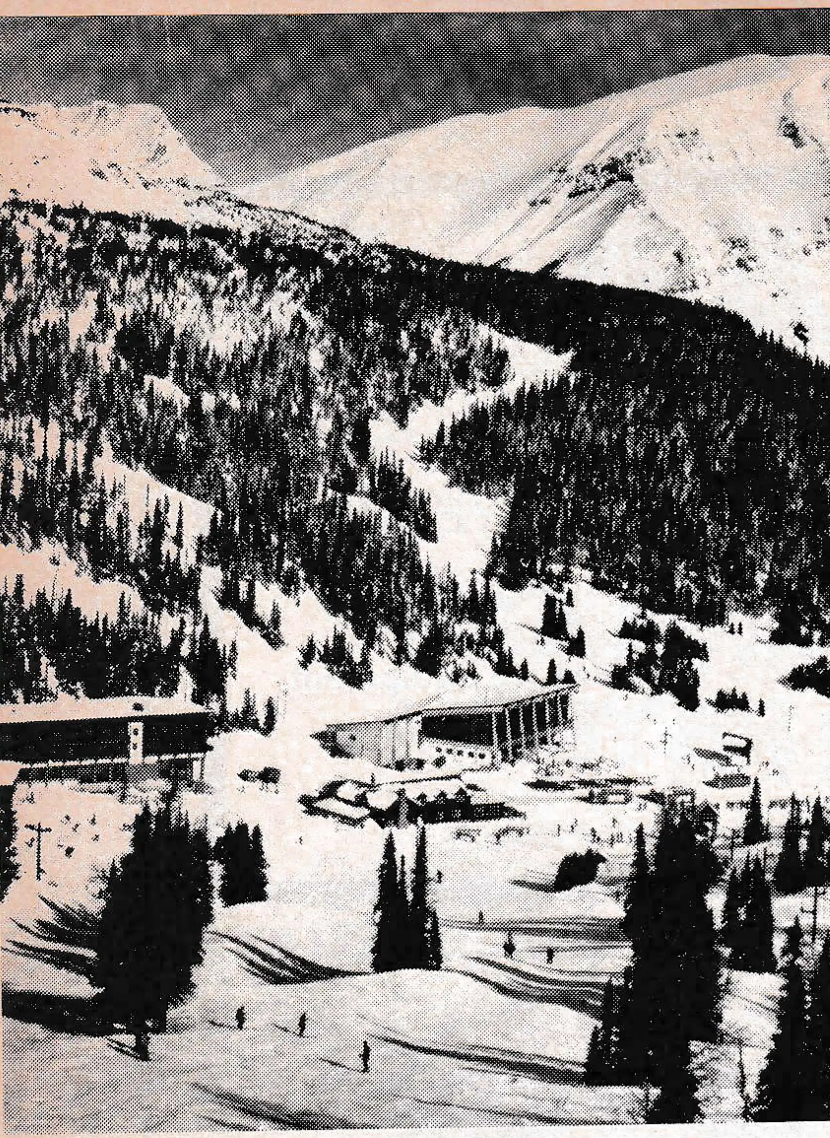
The booming oil economy of Alberta, coupled with a rapidly growing Calgary population (77 road miles away), have justified the $25 million, five-year expansion plan that will see a system of 14 lifts and two major day-use facility centers serving two mountains. The area encompasses some 2,400 acres, with a skiable vertical of 3,700 feet.
The 1,800/hour gondola will provide access to the main skiing facilities from the parking lot. Until now, skiers and summer tourists were transported by 44-passenger buses (road capacity, 1,200 + passengers per hour) from the closest car access point (altitude 5,440 feet) to the Village (altitude, 7,100 feet). The route was three miles long, up a winding, difficult-to-maintain, gravel road.
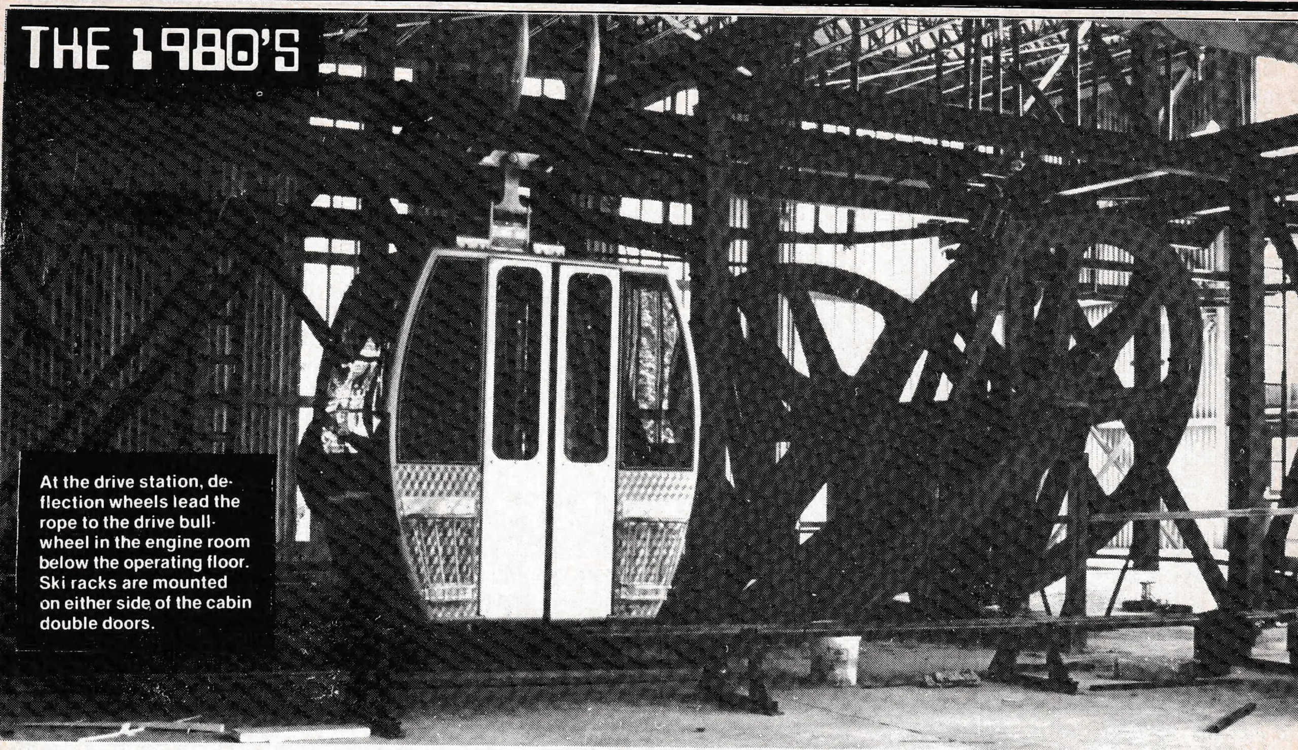
The Von Roll Swiss-designed, Swiss and Canadian-manufactured gondola was chosen for its new grip and system designed for higher speeds and larger ropes; also for its overall simplicity and dependence on gravity for launching and deceleration.
Design
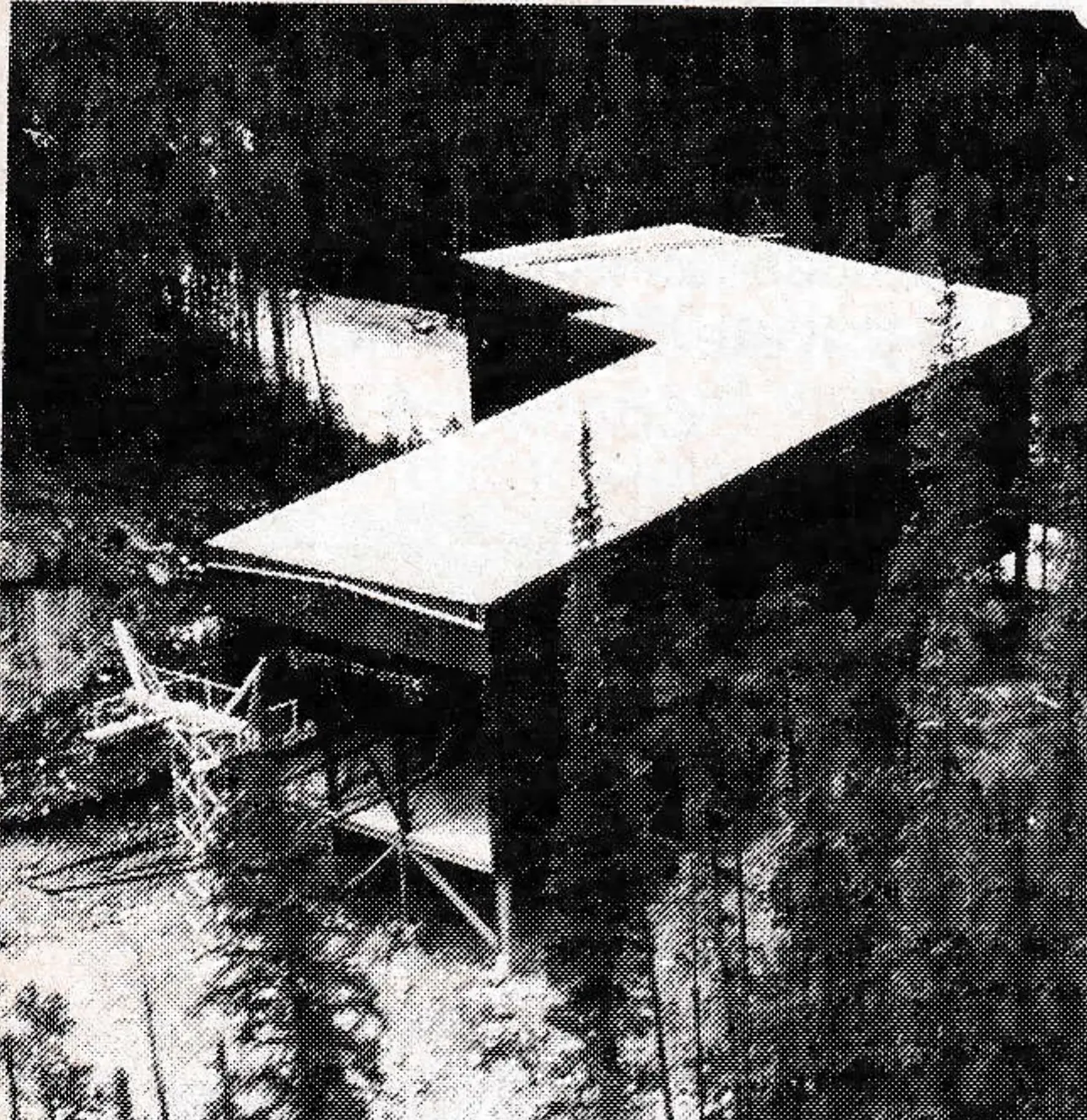
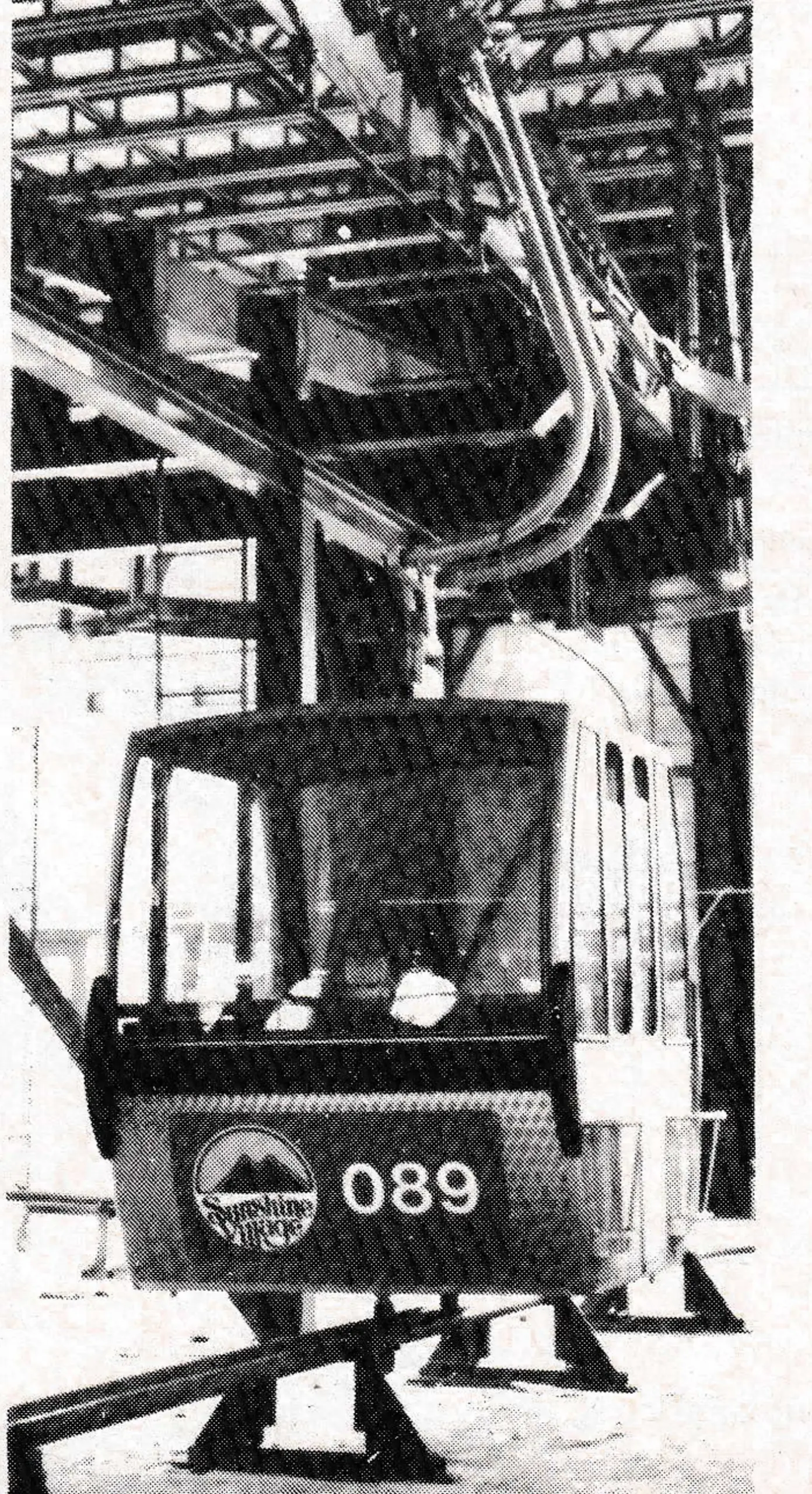
The required capacity demanded a high rope speed. A five-meter/second installation was already being tested in 1977 in Von Roll’s Bern, Switzerland, plant. To avoid a problem cliff on the line, a “Curve Station” turns Section I through a 63° angle. The “Curve Station” houses two pairs of decelerators and launchers, and conveyors on each side carry the cabins around the curve.
Terminal structures allow for loading and unloading, storage of cabins, special bays for freight, plus various amenities depending on location (offices, fully-equipped first-aid room, 500-seat cafeteria, bar, washrooms, etc.). Mid-station (Goat’s Eye) houses both Section I and Section II drive assemblies and main and auxiliary power.
The common engine for both sections is located below the operating floor. Each rope passes over deflection bullwheels which are arranged for a 300-degree wrap on the drive bullwheels.
Grips are designed specifically for high speed, and the gravity system requires long ramps. The gripping force of Von Roll’s grip is provided by the carrier weight via a bell crank system arranged in a horseshoe shaped housing; it is independent of the inclination of the rope.
The clamp is opened by lifting the cabin; i.e., releasing the weight. This new rope grip has a locking device which allows no relaxation of the grip-force when vertical oscillation occurs.
Line towers consist of 37 lattice-type, hot-dipped galvanized steel, from 37 to 124 feet in height. Foundations were of four basic designs varying with site specifics (soils, rockbed, terrain, wind loads).

Roller batteries consist of six- or eight-sheave assemblies equipped with breaker-bar safety switches which are activated by displacement of the haul rope from its regular path (heavy sheave system) or by rope contact in the catchers.
| Section I | Section II | |
|---|---|---|
| Ropeway Length | 8,170′ | 6,139′ |
| Ropeway Rise | 1,179′ | 452′ |
| Transport Capacity | 1,800/hr | |
| Cabin Capacity | 6 persons | |
| Travelling Speed Max. | 1,000’/min. | |
| Carrier Interval Min. | 12 seconds – three cabins can be loaded at once. | |
| Carrier Spacing Min. | 197′ | |
| Haul Rope | 1½” Ø – 6 x 19 Seale, Lang’s Lay/Sisal Fibercore | |
| Bullwheel Ø | 9.8′ | |
| Tower Sheave Ø | 15.7″ | |
| Number of Towers | 23 | 14 |
| Number of Sheaves | 336 | 208 |
| Track Gauge | 16.4 | |
| Counterweights | 40 tons (10-ton tension) | 64 tons (16-ton tension) |
| Number of Cabins | 200 | |
| Curve Station Angle | 63°2′ (deflection from 180°) | |
| Mid-Station Angle | 21°52′ | |
| Main Drives | DC Motors – SCR Control | |
| Peak Power | 315 kw | 525 kw |
| Continuous Power | 200 kw | 370 kw |
Installation
Heavy logging was done in May, 1978, over snow by tracked skidders and by helicopter, where sidehill prohibited use of skidders. Line foundations were started July 20 from the top where snow was to come the earliest, employing 20-odd men until January, 1979. Terminal buildings were completed over the winter months, with finishing done through the summer and fall. Von Roll started terminal installations in May, 1979, through October with a crew of eight. Garaventa (Canada) started tower assembly in May, with actual erection by helicopter taking four days. They used a Bell 214 helicopter (6,000 lbs. lifting capacity at high altitudes) flying shafts in up to four sections, and heads in one unit. Haul rope splices were made in August. Six electricians arrived in August and will be kept busy until start-up time.
Electrical Equipment
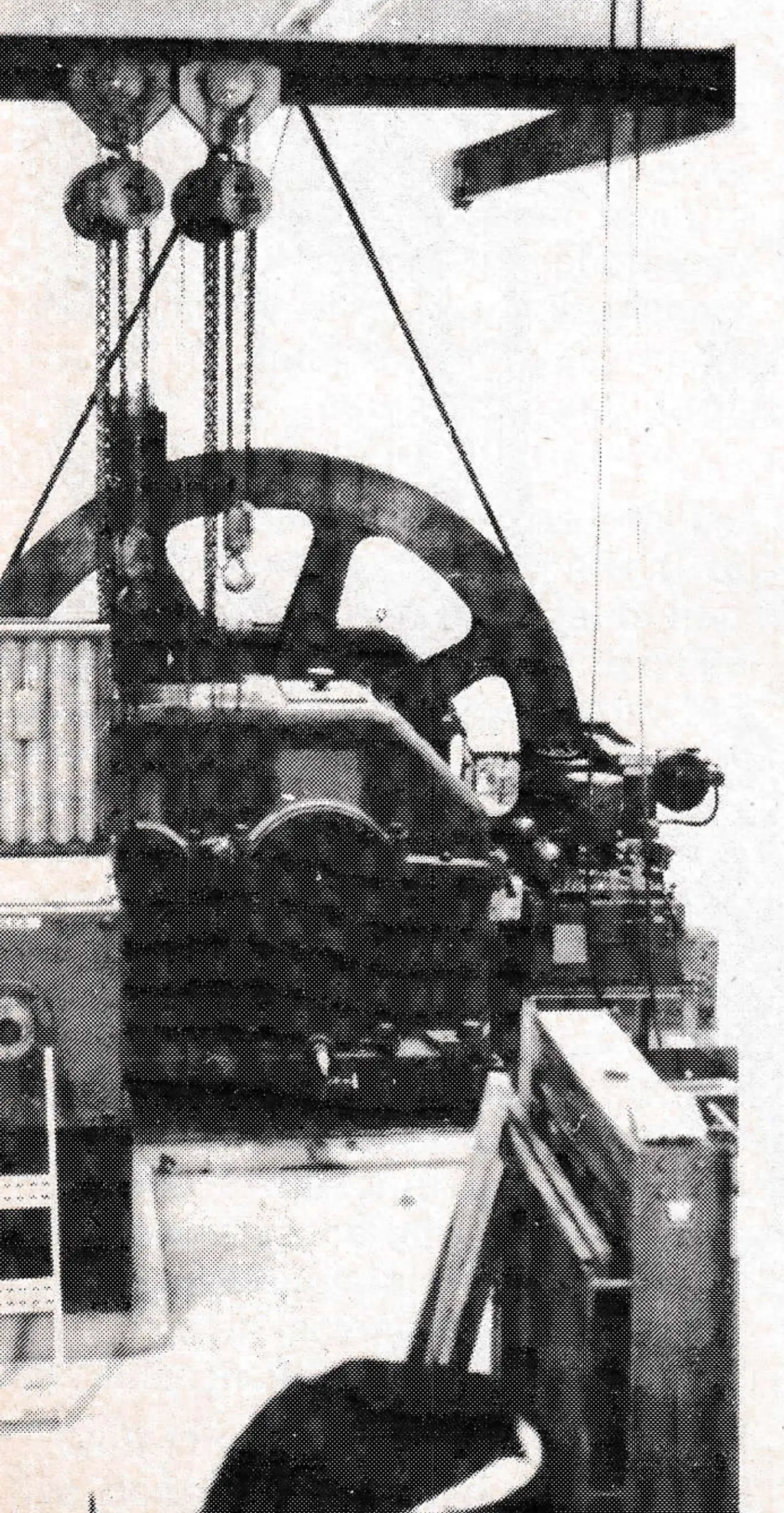
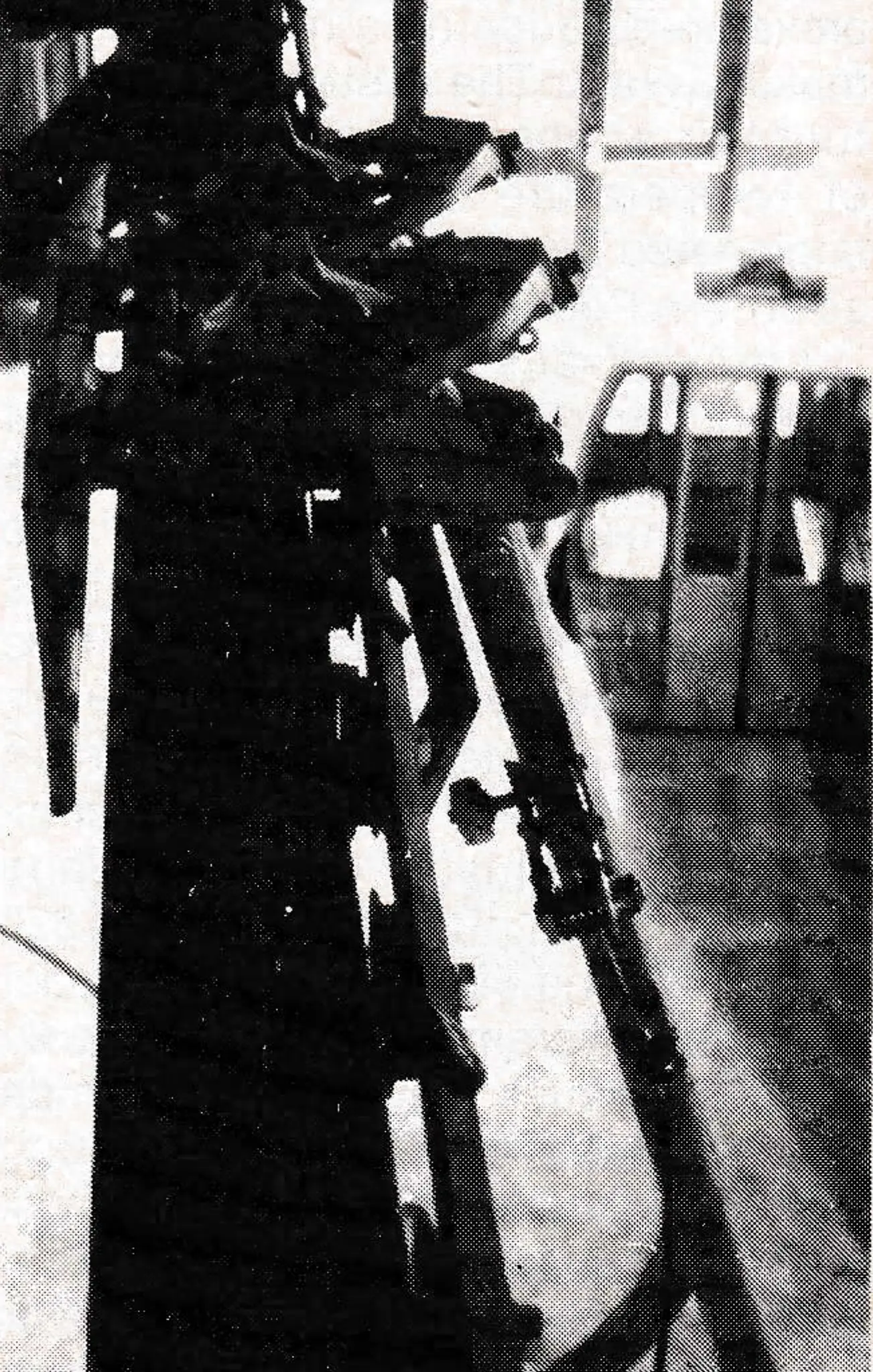
The main drives are DC motors with SCR controls. These motors drive the bullwheels through Hamilton gearboxes. Should there be main motor or gearbox failures, smaller Hamilton gearboxes, driven by hydraulic motors, can operate the gondola at 40% of maximum speed. These hydraulic motors are powered by a hydraulic pump driven by a 6V 92T Detroit Diesel.
In the event of a power failure, a 625 kw generator driven by a 16V 92T Detroit Diesel will provide alternative power to the main control panels so the gondola can be operated at 80% design speed. Although the gondola was designed to operate at 1,000’/minute (5m./second), it may be run at any speed, with synchronized decelerators and accelerators.
The electrical integrity of the entire system will be visible on control panels equipped with light systems in the operators’ rooms. There are two main panels: a conveyor control panel (adjustable speed, stop, reverse), and safety system problem-detector for terminal and line assemblies. These panels are in all four stations.
The safety system monitors all the following conditions of operation. For example, excessive wind speed, or a grip not in correct position when the gondola is due to be attached to the rope will cause the gondola to be stopped.
Safety Devices
- Anemometer
- Haul Rope Ground Detectors
- Entry Supervision
- Door Interlocking
- Tower Breaker Switches
- Magnetic Latching Device Impulse Detector (Carrier Spacing)
- Grip Position
- Grip Lock Release
- Rope Position
- Exit Gauge
- Grip Locking
- Exit Supervision
- Proximity Switches
- Gondola Accumulation
- Overspeed, etc.
Avalanche Zones
Two towers and the rope between them lie in avalanche zones. Tower locations were chosen where shafts were least likely to be hit. Special foundation designs were necessary with 15% total concrete of all the tower foundations in one of the two towers. Earth mounds and gabion walls were erected directly uphill from the shafts. Wind loads of 120 m. p. h. expected in avalanches have been taken into consideration in the design of these two towers. When avalanches are triggered, manually-set clamps are used to retain the rope on the sheaves; safety switches prevent rope movement unless the clamps are locked clear.
Ambulance Cars
Two specially designed ambulance cabins are provided for transport of injured skiers. These carriers will accommodate two stretchers, two attendants’ seats, oxygen, etc.