


This is the third of three articles on maintaining ski lift DC drive motors. The earlier articles (in the 1996 May and September issues of SAM), covered ways in which savings of $4,500 to $40,000 per lift can be realized by extending the time between motor overhauls (dollar savings being largely a function of motor size).
To extend the intervals between overhauls and achieve savings, the following five factors impacting on motor reliability were listed in the earlier articles:
- 1) Motor design, operation and environment.
- 2) Inspections and cleaning—general preventive maintenance.
- 3) Conducting and analyzing the results of predictive testing, motor condition testing and monitoring performance.
- 4) Lubrication—using the correct type and doing it right.
- 5) Quality overhaul—specify what you want done; do not assume it will be done.
This article covers factors two, four and five, which were not covered in the previous two articles. A chart summarizing all the recommended maintenance, testing and monitoring to provide a basis for overhauling motors based on condition is also included.
Preventive Maintenance Schedule
The following are routine preventive maintenance actions that should be performed:
1) Daily during operations (include in operator checklist/log): check motor to be sure it is clean and dry and has no unusual noises; check operating temperature at or near established normal temperature; check bearings for normal temperature (use thermometer), vibration (feel) and look for grease coming out of bearing on outside of machine.
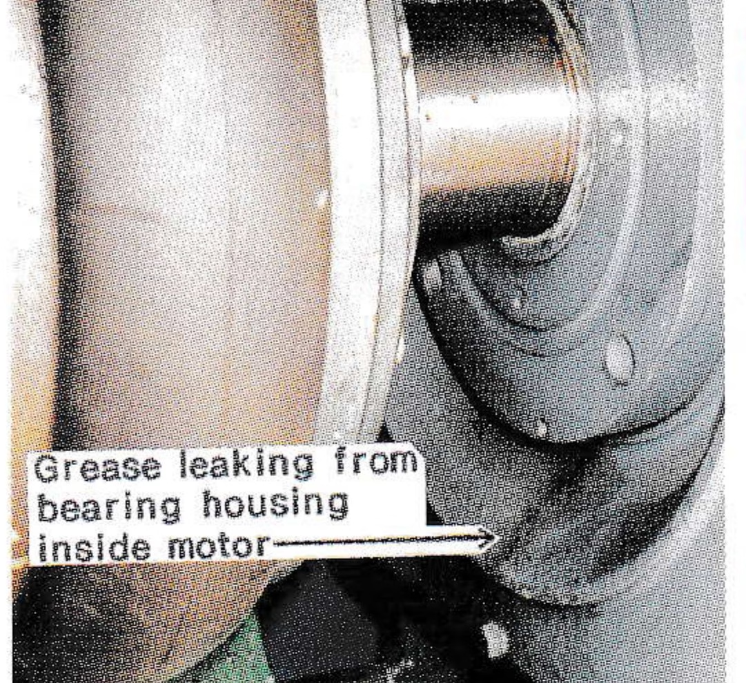
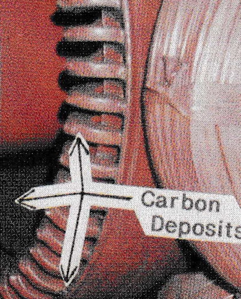
2) Weekly or a minimum of every two weeks in season, with motor shut down and covers removed: review daily operator checklist or logs; inspect bearings for grease leakage—which is generally a sign of lubricant breakdown probably caused by overgreasing—and if evident, schedule a cleaning and correct relubrication to avoid a possible bearing failure; check evenness of commutator color, evidence of streaking, cutting, burning, slot-bar marking, slot-bar burning, excessive carbon, high mica, buildup of carbon in mica slots, evidence of flashover, carbon buildup behind the riser.
3) Monthly in season, with motor shut down and covers removed: check brushes for length (uneven brush wear), chipped edges, copper imbedded in face, frayed or broken pigtails and ability to move freely in the holder; check rigging and cables for carbon tracking; check windings looking for insulation cracking or chipping, heavy deposits of carbon or grease, evidence of arcing or burnt spots; check ventilation filters, if installed. A good rule of thumb is to hold the filter up to a light and, if very little light comes through, change it.
4) Annually (off-season) with the motor shut down: do a detailed inspection of all visible components; measure and record the length of all brushes and compare with previous readings to determine if there has been an increase in wear, and check length against minimum allowed. (The accepted maintenance practice is to replace brushes if the length is half the original.); clean out visible carbon, grease or dirt with lint-free cloths; if ventilation flow is across the commutator and through the motor, then once a year at a minimum, use a vacuum and/or low-pressure air to clean out carbon dust in between the main fields, interpoles and rotor internals, if accessible. Before, during and after cleaning, perform the Insulation Resistance-to-ground test. Carbon may be blown into places that result in lower Insulation Resistance. If this happens, continue cleaning until the low reading is eliminated. It may be necessary to develop special fittings in order to vacuum the space between fields, interpoles and frames, and the same applies to air usage to effectively clean out the machines. Flexible plastic pipe of various sizes has been used to good effect by taping it to the end of the vacuum or air hose. Always make sure the machines are warm and dry before cleaning.
Commutator Inspection Hints
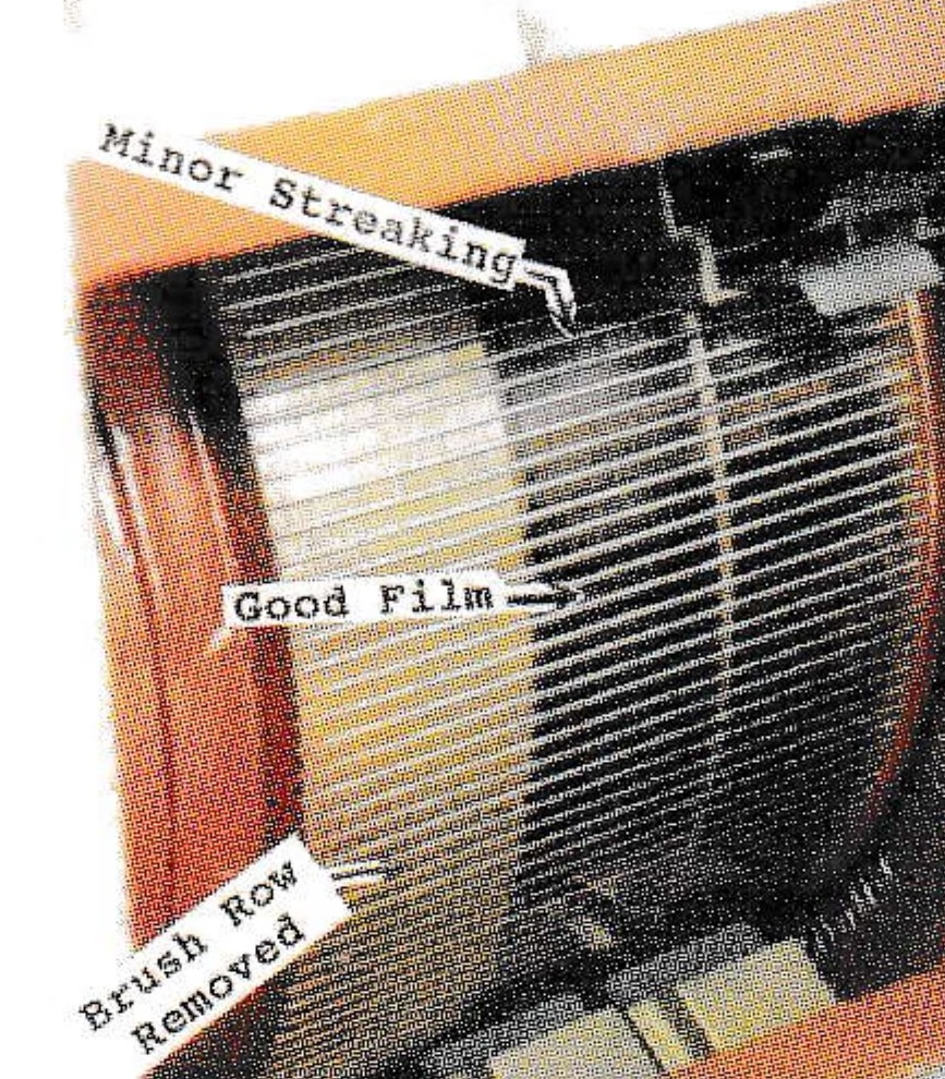
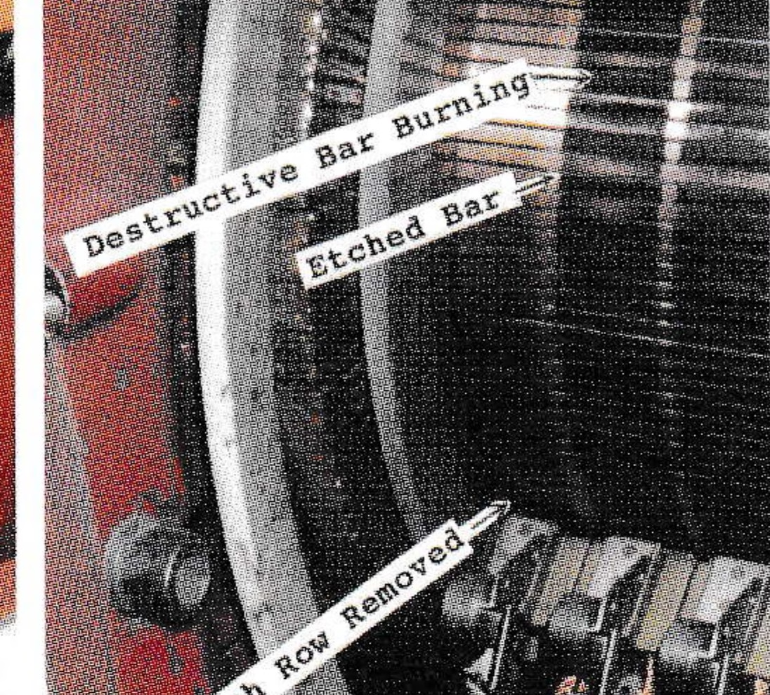
Inspection of commutators is both an art and skill. The color of the film is not as important as uniformity, although a dark bronze is generally thought to be the ideal. Differences in film uniformity vary from streaking to raw copper threading and darker bars to burned and etched bars. On commutator’s areas where threading, bar burning and etched bars exist, there is no commutator film left and a high-resistance interface exists. This causes more heat to generate and eventually flashover between bars will occur, often due to copper drag (melted copper being dragged behind the bar).
Threading is much more serious than streaking, but visually the difference is not obvious. If a fingernail is dragged across a bar perpendicular to the streaks, a thread-like surface will be felt if threading exists. Threading, unlike streaking, means that arcing has broken completely through the commutator film and is machining fine cuts into the copper.
The non-destructive slot-bar pattern normally shows up in marks all the way around the commutator and occurs every second, third or fourth bars. It is related to the number of conductors in the armature slot and, thus, is an electrical characteristic of the machine, which is normally not harmful unless it is accompanied by burning and etching of the bars.
Slot-bar burning or etching results from heavy arcing. Generally, the burning starts at the edge of a bar and, in time, will cover the entire bar. A common cause of slot-bar burning is the brush rigging being off neutral.
The above description barely touches on the complex subject of commutator condition and film. However, even this brief outline can indicate when something is wrong and an investigation or help is needed.
Commutator Cleaning
Normally the commutator will require cleaning if it has become contaminated or excessive arcing is occurring resulting in an extremely dark commutator film. Contamination may be from grease, paints, cleaners or other chemicals. If the film is a color other than a shade of brown or bronze with heavy arcing present, or is streaked with darker areas, then cleaning is in order.
The most frequently used tool for cleaning a commutator is a soap stone. Unfortunately, this should be the tool of last resort because it completely removes the commutator film, exposing raw copper. The use of a soap stone, even in the hands of an expert, also may result in an uneven commutator surface. When the motor is put back into operation, a new commutator film must be formed and during film formation, brush wear will be high and may be aggravated by an uneven surface. The uneven surface will probably get worse and will be a factor in motor failure.
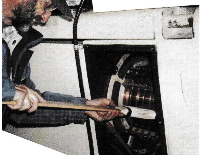
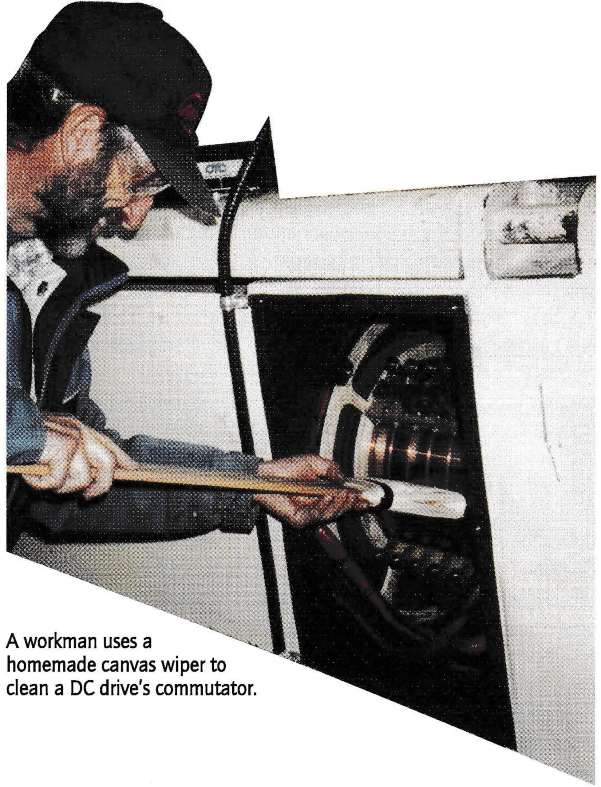
The first tool to use in cleaning a commutator should be a canvas wiper, which, using light pressure, is run back and forth on a running commutator. As the contaminate is removed, the canvas will become dirty, but soiled strips can be cut off until they show little or no contaminate being removed.
A canvas wiper can be made in-house by buying untreated canvas from an upholstery shop. Cut the canvas into one to two inch strips of approximately 12 inches in length and wrap 20 to 30 of these strips over one end of a hardwood board that is two to three feet in length, one-half inch thick and the same width as the strips. Secure the canvas strips with one rivet through all the strips or insulation tape on each strip as it is wrapped over the end. If a rivet is used, be sure to cover it with insulation tape.
After using the wiper, cut off the last strip used and cover the canvas portion in an air-tight poly bag. Also store spare canvas in an air-tight container until needed to keep it clean so it will not contaminate the commutator as it is used.
If the canvas wiper fails to clean the commutator satisfactorily, then use a flexible abrasive that comes in a number of different sizes. The 5/8 inch x 1 inch x 5 inch size is used on small motors and the 1 inch x 2 inch x 5 inch is used on larger motors. Flexible abrasive is like a rubber eraser, both in appearance and use, but its composition contains no conducting material. To remove contamination, hold the material on the commutator while it is running. It will remove commutation film and, if done carefully, will not take it down to raw copper as a soap stone does. The 1/8 inch x 1 inch x 5 inch size is also very useful in cleaning electrical contacts.
Flexible abrasive can usually be found at electrical supplies stores, but if not available locally, sources include Ideal Industries, Inc., Sycamore, Ill., and IDI Electric, Ltd., Ajax, Ont. under the trade name of Powr-Polish.
As a last resort, a soap stone can be used by an experienced mechanic using a fixed jig, which will minimize the danger of ending up with a wavy commutator. A vacuum should be used simultaneously to keep the conducting material from entering the machine.
Proper Lubrication
For most ski lift drive motors, annual greasing is sufficient. More often than not, motor bearings fail because they have been overgreased when someone did not know how to do the job properly. For this reason, I recommend that only electricians grease motors, and that they remove grease zerks and install a grease plug after greasing.
| Performance Frequency | Motor Status | Action |
|---|---|---|
| Daily in season | Running | Check temperature, unusual noise, vibration, arcing. |
| Weekly in season | Shut Down | Inspect commutator, bearing housing for lube leaks, review daily log inspections. |
| Weekly off season | Running | Run motor loaded (lift running) for 15 to 30 minutes. |
| Off season | Shut Down | Keep motor strip and space heaters on. |
| Monthly in season | Shut Down | Detailed inspection: brushes, cables, windings, vent filters, commutator, clean as necessary. |
| Monthly year round (min. three times year) | Shut Down | Insulation Resistance test. |
| Three times a year (min. annually) | Running | Conduct vibration measurements. |
| Annual off season | Shut Down | Detailed inspection including cleaning. |
| Annual off season | Shut Down | Conduct polarization index test. (Ski Area) Conduct dielectric tests; High-Voltage DC, surge comparison and voltage drop. (Contractor) ** |
| Annual off season | Running | Lube motor bearings. |
| As necessary | Running | Clean commutator with canvas wiper when it appears contaminated. |
** For smaller motors (below 200 HP), dielectric testing will not be cost effective, but hidden defects identified are important in making an off season overhaul decision.

These motors are generally operating at 1,800 RPM, which is a much higher speed than any other equipment on the lift, so a grease that will not break down at high speeds is required.
To properly lubricate, do the following:
- 1) Make sure you are using the right grease and it is the same that has been used in the past. (Normally what the manufacturer recommends.)
- 2) Remove both grease plugs for each bearing and install a grease zert fitting in the top plug hole. If both plugs are not removed, the bearing will be overgreased. This a common cause of overheated bearings and subsequent failure.
- 3) Pump new grease in (preferably with the motor turning) until new grease comes out of the opposite plug hole.
- 4) Run the motor for 20 minutes with one grease plug (the lowest) removed.
- 5) Remove the grease zerk and install both grease plugs.
- 6) With the motor stopped, check inside to see if any grease has pushed through the seal into the motor internals.
- 7) Clean up and clear out all excess grease.
Quality Overhaul
The following 14 points summarize the elements of a good overhaul. It’s important to visit the shop several times during the process so the shop supervisors and mechanics know you want the highest quality work and attention paid to all details.
1) Visit the shop before putting the motor in their hands to check their quality control. You can tell a lot about the quality of workmanship by observing the ongoing activity.
2) Find out what kind of warranty the shop offers. They should provide one- to two-year warranties if they have good quality control, do necessary pretests and correct not only the known problems, but hidden ones as well. If they are reluctant to provide this type of warranty, try to find out why and/or look for a shop that does. Such a shop may not be as conveniently located and may cost a bit more, but nothing is more frustrating than to install an overhauled motor, have it fail in less than a month and then have to pay for additional repair. It happens frequently.
3) Have the shop thoroughly test the motor when it is brought in. This includes Surge Comparison Testing, AC and DC Hi-Pot tests and Voltage Drop tests on the fields and interpoles. Insist on a detailed report of findings and repairs. Ask to see what they normally supply to other customers, make sure it meets your needs.
4) Ideally a shop should have a load-test capability. One way to test a DC motor is run it as a generator up to full load. Find out how the shop checks and sets the neutral plane before the motor is returned to you. If they do it solely by the match-mark method, you may want to look for a shop that does it electrically.
5) Insist on Vacuum Pressure Impregnated (VPI) insulation.
6) Make sure the new brushes are the same as those being replaced unless you have a reason to change.
[The remainder of this list (points 6–14) continued on a page not included in the archive scan.]
A Cost-Saving Case History
This ski area has three fixed-grip lifts. Currently, Lift 1 has been in operation for 13 years, Lifts 2 and 3 for 10 years each. Although the lift manufacturer recommends motor overhaul every four years, the area technicians have followed the motor maintenance and testing recommended in this series of articles, with the exception of the Dielectric tests. As a result, motor overhauls have been based primarily on condition, not time, and no motor failures have occurred during a ski season.
Each lift has had one motor overhaul: Lifts 1 and 2 after five years, and Lift 3 after two years. At the beginning of the 1996-97 season, the motors had been in operation since their last overhaul for seven years, five years and eight years respectively.
If the four-year cycle had been followed, seven overhauls for the three lifts would have occurred instead of three. Thus, four overhauls were avoided at an estimated cost savings of $17,000. This value is based on charges for routine overhauls of the motor sizes involved as specified by the repair facility used by the ski area.
The Lift 3 motor overhaul after two years illustrates the importance of testing new motors when first installed. The usual demands on the staff caused by the installation and operation of two new lifts resulted in no time to do insulation resistance (IR) tests on the motor during the first season. You say the motor was new, so why should they have tested it? Well, the first IR test on the armature circuit resulted in a 0.08 Megohm reading, almost a dead short-to-ground.
After two days of cleaning, first with rags, then a vacuum and finally using low pressure air with the vacuum (while taking frequent IR readings during the cleaning), the insulation resistance suddenly jumped to 35 Megohms. The sudden jump indicated that carbon was finally blown out of a crack or hole in the insulation system, breaking the path-to-ground.
For a motor with less than three months of operation that season, the only possible conclusion was a manufacturing defect in the insulation system. The area made the decision to monitor the motor closely, clean it frequently and run it until cleaning and IR testing indicated an overhaul was necessary.
After the second season, the IR reading was holding steady at 60 Megohms. Unfortunately that fall, a family of mice moved into the motor. When the machine was first run after this event, it was immediately apparent that the motor was an expensive mouse trap. The decision to overhaul after this was a no-brainer. But the overhaul consisted only of cleaning, bearing replacement and varnishing. —N.H.