

Every year there are bad accidents on rope tows; all-too-often they are lethal ones. The villain is rope spiraling. In 1964 SAM carried a major article by Verne Despain of the U.S. Forest Service which showed how it could be controlled by adjusting the skew of the sheaves. Fred Becker of Big M, Mich., contributed a valuable suggestion on “de-spiraling” in the Summer ’73 Idea File. This latest by Walt Stopa marks another important advance—hopefully the final solution—to this nagging problem.
Most ramway codes (including ANSI B77.1) limit fiber rope spiraling to no more than one revolution in 200 feet. This has been exceedingly difficult, if not impossible to achieve and maintain by most areas operating fiber rope tows.
The basic problem is one of adjustment. Few sheaves are constructed to allow alignment while the rope is fully tensioned and moving at operating speed. Since there are numerous sheaves, and the alignment of one sheave has an effect on all the others, alignment has always been a time-consuming operation. Furthermore, since wood poles are normally used for supports, any bending, twisting, or rotating in the ground of the pole changes the alignment of the sheaves. The results are both obvious and frustrating.
At Wilmot Mountain, after repeated disappointments, we found the answer after we spent more than a month on a ‘system analysis’. First, we determined that if all sheaves were in reasonably close alignment, the spiraling of the rope could be entirely controlled by the top break-over sheave on the loaded (uphill) side of the tow. Second, it made no difference whether the drive and tensioning device were at the top or bottom of the slope. That sill left the problem of adjusting the sheave while it rotated. Third, what looks like a good alignment when the rope is not moving, is not the same thing as proper alignment when the rope is in operation. Fourth, there is a minor difference between the adjustment that is made before the season when the rope is in contact with the bare ground, and the in-season adjustment that is made when the rope is in contact with snow, or hanging free between skiers.
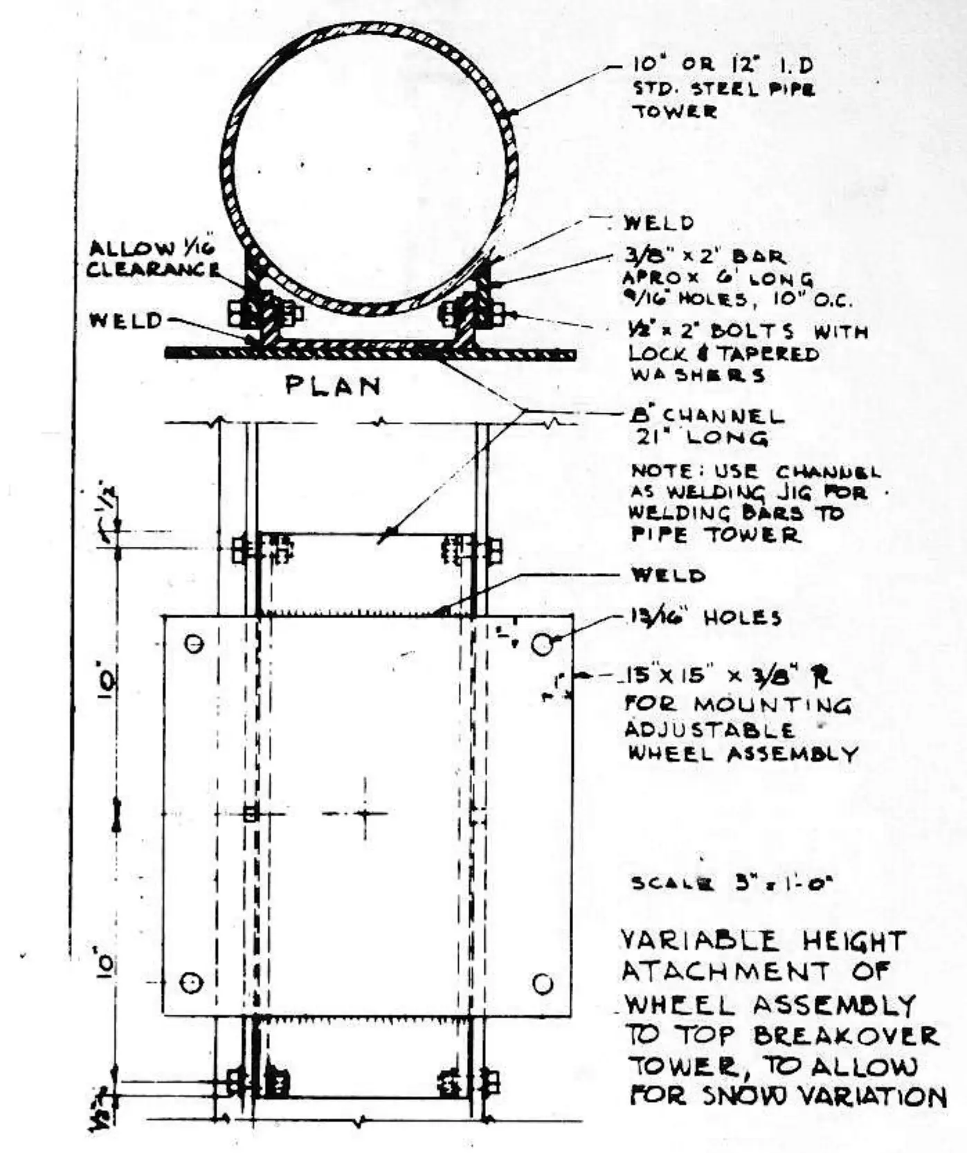
Our main problem was now well defined. We had to design a simple, inexpensive method which would allow for adjusting the sheave while the rope was in motion. The sketches indicate the best of several methods we used to achieve the desired effect. The esential part of the mounting device consists of two plates, 15” square, with a bolt welded near each corner. The thread of the bolt projects about 2½” past the plate, and must be threaded for its entire length. Next, a nut is placed over the bolt to within ½” of the plate. A lock washer and then the second plate is placed over the four bolts. Another set of lockwashers and nuts is placed over the four bolts. Another set of lockwashers and nuts is placed finger tight against the second plate. Prior to this, the pole mounting device and sheave are fastened to their respective plates. Since most installations use automobile wheels for the sheaves, the attached sketch (1) shows a typical hub welded to the second plate. After the sheave is firmly attached to its support, the rope is installed, the tow motor started and the lift run at operating speed. Then the process of minimizing spiral beings.
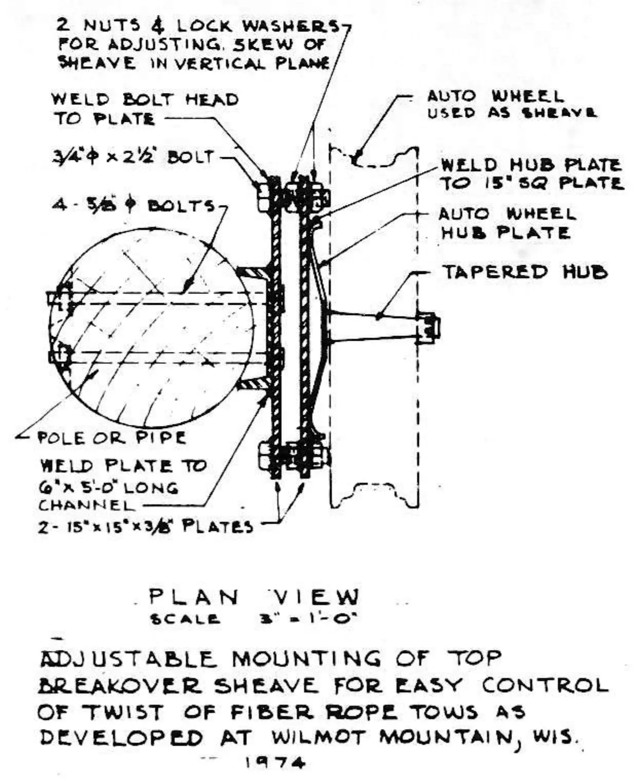
We have found that it is necessary to skew the wheel only in the vertical plane. While the rope is rumming, it is very simple to make the adjustment by using two of the nuts holding the second plate. It was very interesting to discover that by means of rather small adjustments, the rope could be made to spiral at least one revolution in 25 feet. As the skew was changed, the rope would continue its trip with absolutely no spiraling in the entire slope length. By continuing the skewing, the rope could be made to spiral in the opposite direction. We, therefore, feel that this method gives quick, easy and complete control of the spiraling of a rope. Should changes take place between the fall and winter operation, any spiraling which occurs can be compensated for in a matter of minutes.
Following are some additional conclusions we arrived at as a result of our ‘system analysis’ and subsequent developments.

1. Even though some tows required considerable ‘skew’ to prevent any spiraling, we have not noticed any reduction in the life of the rope.
2. If automobile wheels are used, the type selected should have a symmetrical groove. Most recent wheels have one flange at a 45-degree angle while the other is nearly vertical. This is not a satisfactory sheave. If a rope is deflected toward the 45-degree flange, it will tend to ride up on this side and in all probability cause spiraling.
3. Having had over 35 years experience with rope tow installations and operation, we believe that most of the problems and injuries involving rope tows were wholly or partially caused by spiraling of the rope. We have also found that even one revolution between the bottom and top of the tow path is apt to cause difficulties.
For many years we, like other tow operators, have experimented with more complicated devices than these shown. It is a bit embarrassing to admit it took all this time to develop a simple and economical one that may ultimately save a life