


Resumé
2. Excessive chair swing can cause operational problems and is subject to the physical laws governing pendulums, springs, vibrations, etc. The following factors are involved with the problem:
- a. Traction rope weight
- b. Traction rope tension
- c. Traction rope speed
- d. Traction rope tower sheave diameter
- e. Chair weight and chair spacing
- f. Chair passenger weight
- g. Chair height and chair interval
- h. Type of chair clip or grip
- i. Tower height
- j. Tower configuration
- k. Tower appurtenances such as lights
- l. Span lengths
- m. Type of prime mover and drive machinery
- n. Type of traction rope tensioning system
- o. Location of drive and traction rope tension machinery
- p. Configuration of loading ramp and after loading ramp
- q. Exact loading point
- r. Chairs equipped with chair dampers
3. Out of all of these factors, the only ones subject to easy change are the last three, p., q., and r. As a rule, the proper application of these three variables will solve chair swing problems and turn a “tiger” into a “kitten”.
The chairlift as it is used today as a high capacity transport vehicle for skiers is a marriage of the ability of a machine and the human being. The system depends upon the skier having a certain ability, so that the chairs can be loaded while they are in motion, thus permitting the chairs to be permanently attached to the traction rope.
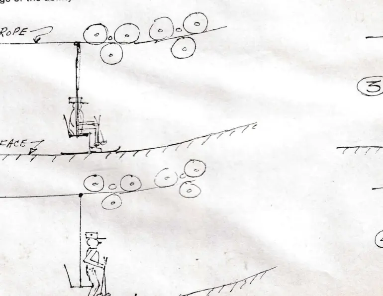
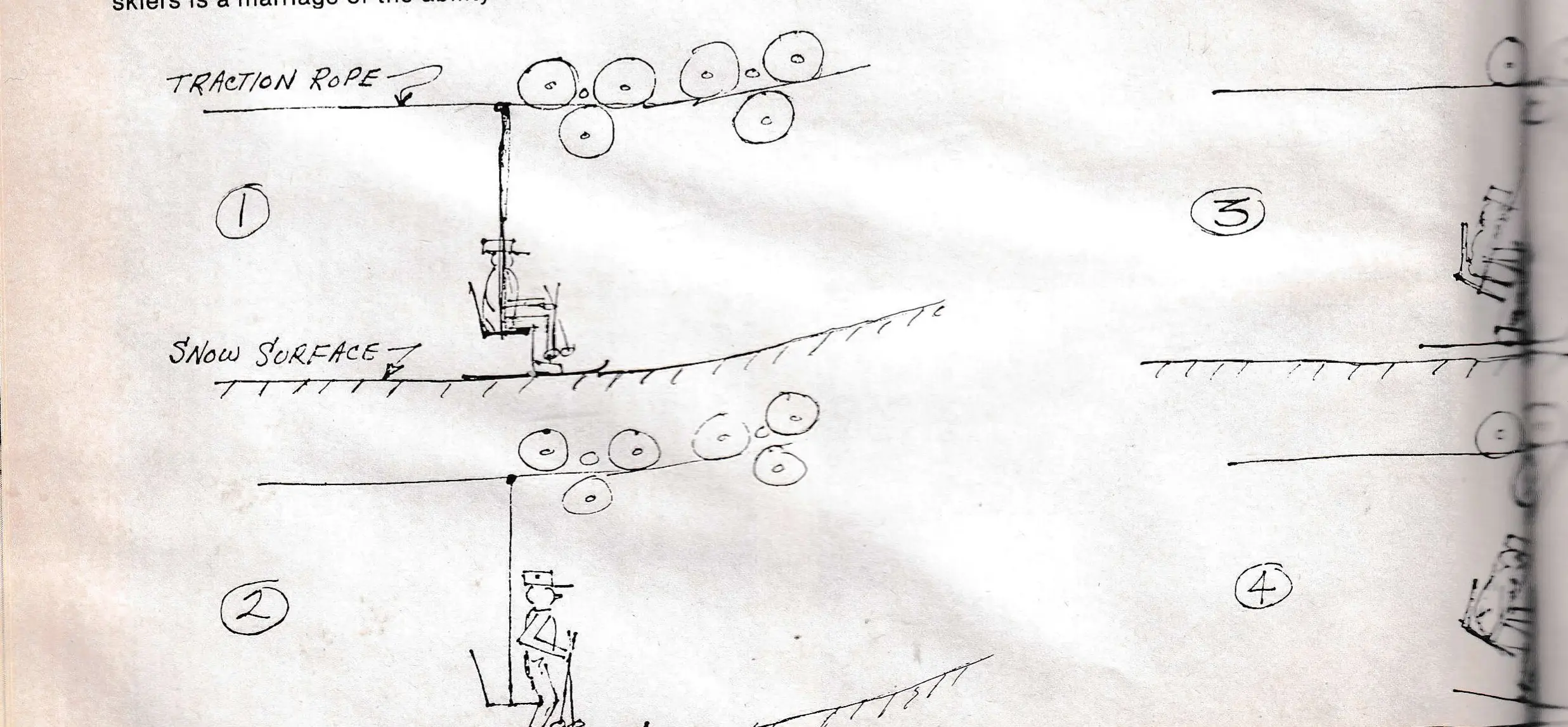
Since the skier is actually loaded into a chair that is traveling at the speed of the traction rope, it is necessary for the chair to impart the energy necessary to the skier to attain the velocity of the traction rope at the loading point. One would think that this occurs in a fairly simple process whereby the chair just comes along, and the skier sits down in the chair and goes merrily upon his way, such as is pictured in sketch #1. This would indicate that the chair does not react with the traction rope and that the chair does not swing back and therefore, everything would be quite docile and no particular extraneous forces would be transmitted through the traction rope during the loading process.
For the modern high speed chairlift, the action as shown in sketches #2-6 more accurately describes what actually happens during the loading process, and we will go through these various steps as follows:
Sketch #2 shows the skier or skiers in the loading position just as the chair approaches them and contacts them at the back of their legs at knee level. The skier in this position, upon contact with the chair seat proper, is stationary and of course has his poles in his hand and is ready to sit down when the chair arrives to allow him to load.
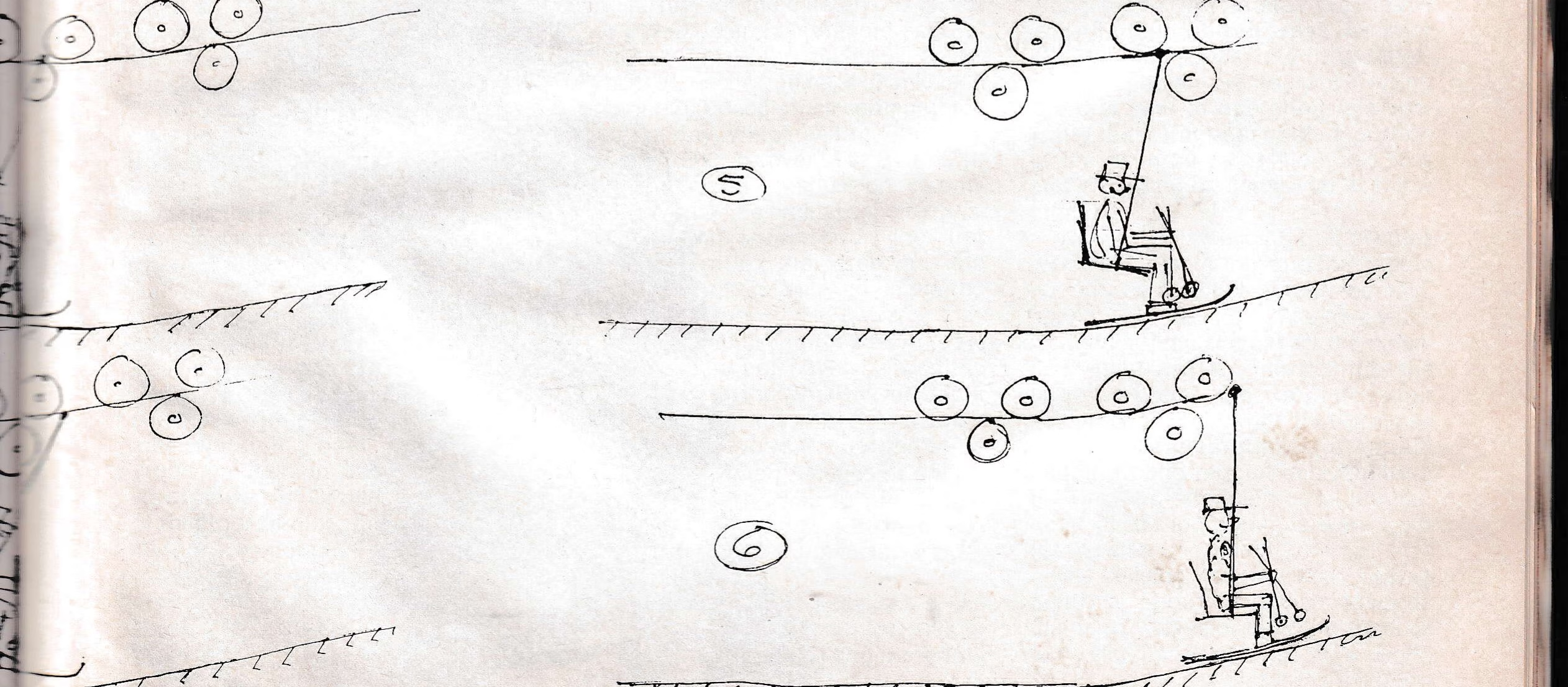
Sketch #3 indicates that a fraction of a second later, the chair attachment to the traction rope has progressed on a short distance, but the chair seat and the skier are, for all practical purposes, at about the same location where the chair contacted the skier. This shows that the skier actually stops the seat part, and in so doing, since the chair attachment on the traction rope will proceed on at traction rope speed, the chair hanger forms an angle with the vertical and exerts an upward as well as a forward force on the skier proper. We will note in observing the skier’s skis that they are actually lifted off the snow surface at this point, and they have, and he has, moved in what is apparently almost a vertical direction upon the initial loading process.
The next sketch, #4, shows the situation as it occurs a fraction of a second later, and this pictures the chair hanger at even a greater angle and the skis and skier’s boots are even higher in the air off the snow level. This sketch is intended to depict the chair at the greatest angle to the vertical that it attains during the loading process. From that point on, the chair will tend to swing forward and propel the skier at even a higher velocity than he has attained at this point. This is due to the fact that the chair acts as a pendulum that is unstably deposed and attempts to go to a stable position where the center of gravity of the pendulum is directly below the support. To progress from the sketch #2 through the sketch #4, we have imparted a considerable amount of energy to the skier that has been supplied by the traction rope. This opposite reaction to the traction rope, of course can present some problems to the chairlift as a whole, since the traction rope is in reality a large spring, and is subject to the physical laws that govern the actions of springs of this type. As an indication of the magnitude of the forces imposed upon the traction rope by the loading of, say two skiers in a double chair on a chairlift, a sensitive recording ammeter or watt meter will be able to show on the recording sheet the exact loading that takes place at each interval when the skiers are picked up.
Sketch #5 shows the skier progressing on farther with the chair coming back to almost the vertical position and the skier dragging his skis along what we call the “after loading ramp”. This action of the skis dragging on the after loading ramp stabilizes the chair somewhat so that some of the swing energy of the pendulum is removed at this point. This helps reduce the effects of the loading impact on the rest of the overall chairlift machine, including traction rope and the attached chairs on the lift.
Sketch #6 shows the skier at the point where the chair has reached the vertical position with him still dragging his skis on the after loading ramp with much of the longitudinal swing of the chair dampened out.
The action of the chairlift proper throughout its entire length is subject to the physical laws that govern the actions of springs, pendulums, suspended spans, cantilevered beams, and the physical laws of vibration of not only structures, but all engineering materials. The classic example that we have all heard of, has to do with the suspension bridge and its resonant frequencies and the disturbance that can occur to a structure of this type when a group of people crossing a bridge, cross the bridge at a certain stepping rate, and all in step, thus creating a great swing or disturbance of the bridge when a certain cadence of the people crossing the bridge is attained that would become resonant with the natural frequency of the structure. We all also know that the solution to this particular problem is to have the individuals walking across the bridge walk out of step at random rates so that their overall disturbance will not become resonant with the natural frequency of the structure.
The chairlift is actually a giant spring in the form of a traction rope supporting a number of pendulums in the form of chairs, that in turn support a variable type load, which in this case is representative of the skiers. The entire system is subject to vibrations and upsetting forces that can become resonant and thus increase the magnitude of the upsetting forces or can dampen, depending upon the frequencies of the upsetting forces and the part of the cycle that these upsetting forces are applied in, as related to past upsetting forces. This is easily demonstrated by when we swing a child in a playground swing, the swing is very easy to increase in magnitude of swing, by merely applying … time of the cycle that the force was applied. This illustrates that in some situations a force applied to a system can either be reinforcing, and thus increase the magnitude of any upsetting vibration, or decrease it when it is in fact a dampening influence.

This applied to our chairlift problem when we exert the added force on the traction rope to pick the skiers up as is done between sketches #2 and #3. When this force is applied at an instant in the cycle, it can increase the swing of a chair immediately ahead or immediately behind the chair we are loading the people in. In other words, if this loading shock is transmitted through the traction rope at a certain part of the cycle, it will tend to make the rest of the chairs on the line dampen out from any swing they have, or if it’s transmitted at another point in the cycle, it can very well cause them to swing. This is particularly true on the light side of a chairlift, and it can occur anywhere on the chairlift, depending upon the other factors involved.
How do we overcome this problem that sometimes occurs with a chairlift whereby the loading of the chairs becomes resonant with the other parts of the system to cause chairswing? One way is to actually change the part of the cycle that we pick the skiers up in, and that merely is to change the exact place of loading by either moving it backwards or forward, so that the upsetting force is applied at a different time in the cycle, changing it from an upsetting force to a damping force. Another way is to help remove the swing energy of each of the chairs by being sure that we have the after loading ramp as shown so that it will help dampen out each of the chairs as it is loaded, thus minimizing the energy they contain after leaving the loading area. We all know that the operation of a chairlift is primarily limited by the amount of lateral swing of the chairs, whether it be caused by wind or some other upsetting force. We also know that due to the types of pendulums and traction ropes and supports we have for these units, a longitudinal swing of a chair, if allowed to continue, can translate into a lateral swing which of course, is the most damaging as far as restricting the operation of the equipment.
Another method to remove the swing energy from the chairs, is to install chair dampers between the chair hanger and the chair attachment to the traction rope so that this swing energy can be converted to heat. These are very effective for chairlifts, and many times what appears to be a “tiger” can be turned into a “kitten” by the mere installation of chair dampers.
Looking back to the sketches again, it will be noted that as we pick up the skiers between figures #2 and #3, the chair hanger has been drawn to be supported on the traction rope sheaves that are attached to the front of the lower terminal or to the first tower at the loading point. When the chair attachment is in fact supported on these sheaves, it is more rigid at that point, and not subject to vertical deflections that would tend to be transmitted on to other spans due to abnormal deflections created by vertical forces during the loading process.
Contrary to this type of loading, if the skiers are actually picked up, say in the middle of a span, eight or ten feet away from a tower support structure, a fairly large vertical deflection is applied to the traction rope which many times will upset not only the span in front of the loading point, but also can effect the entire length of the chairlift.
In the installation and maintenance of the after loading ramp, many areas have found that they are most successful by installing screed boards on either side of the after loading ramp, similar to those used by concrete installers, to actually define and maintain the proper level for this after loading ramp. The after loading ramp of course, must parallel the traction rope and be of such height that the average adult skier will be forced to drag his skis on it during the first forward swing of the chair after loading to help stabilize the chair. This, usually for a 500 foot per minute lift speed, requires about 15 to 16 feet of length. After that point, the ramp can break away and go down at say a 45 degree angle so that the skiers can drop their skis without fear of catching them.
Even with the loading point properly established, and a perfect after loading ramp installed and maintained, it is still desirable in many cases to use the chair dampers so that the rest of the energy will be removed from the loaded chairs and therefore not leave these swinging chairs after the loading point to transmit further energy to adjacent chairs as well as possibly translate the remaining swing into a lateral movement of the chair seat.
Recognizing that the energy of each loaded chair is a function of the speed squared, it is evident that the high speed lifts are much more subject to chair swing problems, etc., than are the slow speed lifts.
Again, to repeat the last item of the resumé, “the proper application of the last three variables will turn a “tiger” into a “kitten.”