

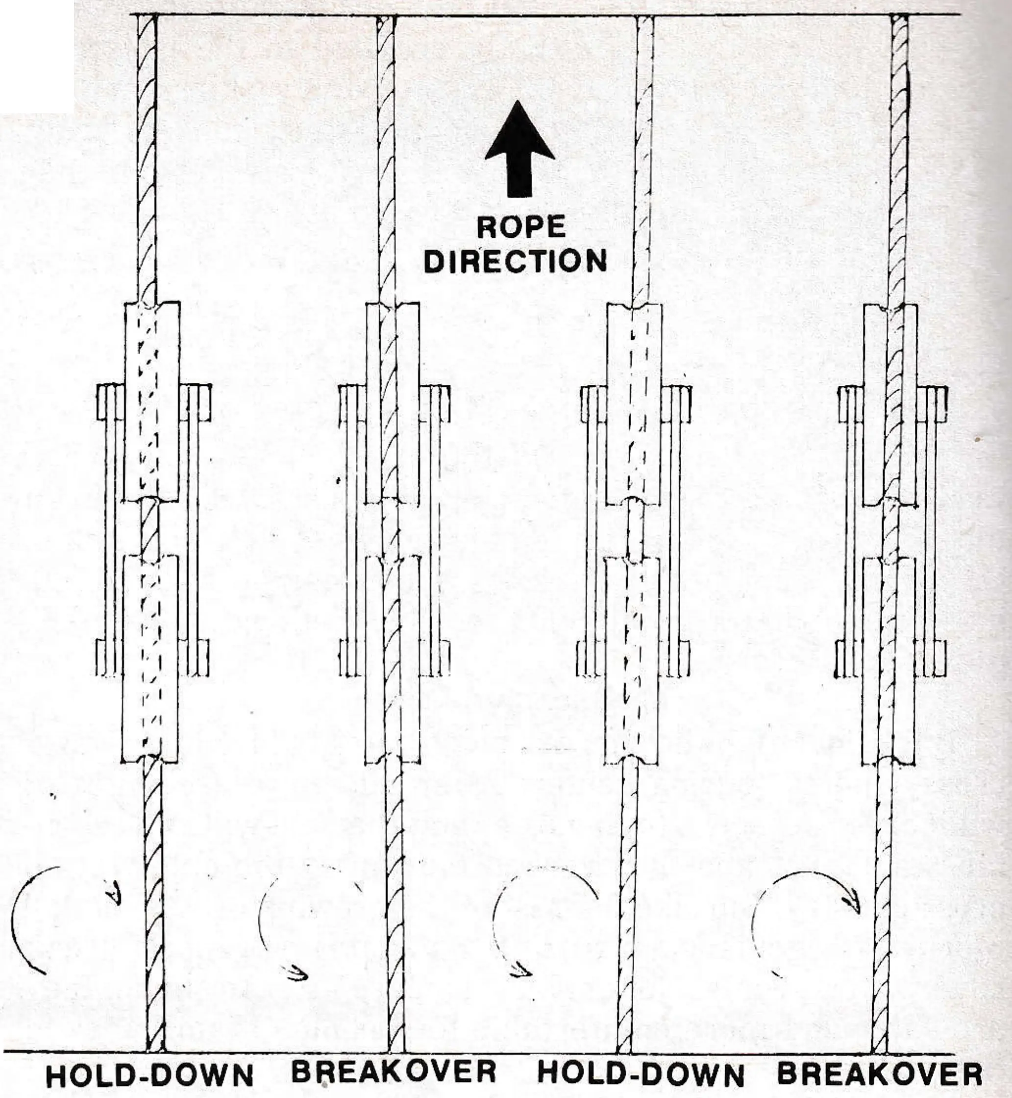
We are talking, of course, about rope to tower sheave and bull wheel alignment where the provisions for making adjustments are sometimes crude or inadequate, and the gauging techniques tricky and not well understood.
Good rope path alignment is more than important: it is essential. While good alignment does not necessarily guarantee a good-running, trouble-free lift, a bad condition of alignment will hand you more headaches than you need, not to mention the danger.
Before the bull wheel chair-swing-restraining-rims were used, there wasn’t much movement of chairs on the cable and, providing the chair grip to cable relationship was in good order, the chairs were not expected to move. If they did, the chances were about ten to one that the cable path was badly aligned and the rope was rotating within the grips.
It seems now, with bull wheel rims containing the centrifugal swing instead of guide rails, that chairs do move along the cable. They move unless they are clamped so tight that the cable compresses and deforms or the clamps are the insert type.
It’s okay if the chairs move within reason. This is the result of the action occurring as the chairs make their turns. But if they travel 15 or 20 feet during a season then you had better have another look at rope rotation and alignment.
Have you seen empty chairs leaning left or to the right of plumb? This could be the result of the chairs having been installed consecutively as their positions arrived at the installing location — the torque in the rope, as governed by the conditions of alignment throughout the lift, being locked up ahead of the first chair installed. Or, it could be a result of a rolling rope as governed and controlled by the tower sheaves or bull wheel toward which the leaning chairs are moving.
When considerations of alignment and a rotating rope are in order, there are a few simple facts that should be understood:
- When a rope is spliced endless, there are a fixed and absolute number of rope lays locked up within the length of this endless cable. Nothing can change this. The lay can be unevenly disbursed, but the count remains unchanged.
- The rope is spliced to a given length. Constructional stretch, elastic stretch and temperature changes all affect the rope length, the lay length and the diameter, but not the total lay count.
- Rotational behavior of the rope is controlled and controllable by the tower sheaves and angles of entry to the bull wheels, which in turn govern the distribution of lay.
- Two things should be considered: lay and footage. While there is a theoretical number of lays per foot of rope length (lay length equals about 6.5 times the rope diameter) the ratio will be altered when conditions of alignment are such that the flow of lay is restrained while footage is passed on, or the lay is passed on ahead of the arriving footage. This is how “lay” becomes unequally distributed.
- There is a natural tendency in a running rope for the flow of lay to be restrained or held back on the approach side of any sheave, bull wheel or drum.
- There is a natural inclination for any stranded rope to unlay under tension. The greater the strain, the greater the tendency to unlay.
It is obvious that when the chair-hanging operation gets under way, the condition of the lay distribution at the chair-hanging station will be a dominant factor. If you are trapping an accumulation of lay between chairs as you progress, it is being robbed from the balance of the rope. As the first chair draws near again, the lay length will be opened up (longer).
Let’s take a quick look at the types of chair-to-cable attachments available. Basically, there are three types: the “positive torque lock,” which has to be the insert type clip; the “semi positive,” which is the external spring loaded grip; and the “full floating,” which is the tapered neoprene sleeve chair positioner within which the cable is free to rotate.
The “positive lock” type is non-forgiving. It provides no opportunity for the cable to “torque relieve.” This is a one way street. When torque forces are induced into the cable, if indeed there are any, the chairs act as torque levers to forceably keep the cable running in a singular plane. They might lean a little, but they won’t let go of the cable. With these, be sure to check the alignment rope rotation aspects before you install the first chair. Once a chair goes on, your best indicator, rotational behavior, is lost.
The “semi positive” arrangement adds up to a battle of forces. The external, spring loaded grips have the ability, unless they are so tight as to deform the cable, to contain a certain amount of torque. So, the cable roll will be counteracted by the grips only to a point. When this point is exceeded the cable will rotate within the grip and partially relieve. In doing so it feeds as much torque on to the next chair which will either accept and keep it or it will not. So the set up for a chain reaction is possible.
Remember too, that even if the grips are all of the same design each does not have exactly the same capability to receive and retain torque.
When the cable rotates within one of these grips, the chair almost always moves back on the cable. I say “almost” always because the flow of lay is usually being restricted by the towers and is being bucked ahead by the chairs. When the cable spins, the grip is threaded back along the lay. (Don’t be misled here and decide to tighten the grips to stop chair movement. Stay with the manufacturer’s specifications).
The “full floating” type — there are still some around — allow the cable to rotate, relieve and otherwise do as it darned well pleases. You can have problems here, though. If some rotate freely and others don’t then the ones that don’t will be bucking an extra load of torque ahead and the chairs may be seen to “lean” or the sleeves turn up damaged. Don’t fail to relocate them when you are supposed to. There is about two feet of cable hidden from view within these sleeves and I have seen rusted, rotten and deteriorated cables under those that were not moved.
Why be so concerned about a little roll in the cable? If the lift line is properly surveyed and the cable path is straight, isn’t this good enough? I would have to say that such an ideal condition is good enough except for the two natural tendencies — the rope to unlay under tension and the inclination for the flow of the lay to be retarded upon contact with any sheave, bull wheel or drum — mentioned earlier. Then there are those “IF’S” to consider.
Anyone who has erected a lift knows that there are plenty of chances to lose the straight line while the forming, pouring concrete, standing towers and adjusting within the limits provided. Straight lines are not easy to hold in the kind of terrain in which lifts are erected. Then there are those lifts in which the bull wheel diameters are smaller than the gauge of the lift. Even if your survey is dead on and the tower roller batteries are perfectly straight your rope will still roll.
So, how good do we have to be? What more can we do?
It isn’t exactly a matter of perfection: it’s more a matter of making final adjustments that will, in the end, keep the roll and the opposing torque forces to a minimum. There is good, understandable reason to avoid over exercising the rope, and for minimizing the wear on those expensive sheave liners. Splices also suffer greatly because of misalignment. If a splice is torqued to tighten or shorten the lay, the tucked strands will invariably be high. When a splice is torqued in a direction to unlay, then the tucks will become tight and low. A splice can stand just so much of this before the condition becomes permanent. It’s all a matter of relative degrees.
If it isn’t a matter of perfection, then how good is “good enough”? While there is no pat answer to this, I can cite a couple of examples.
There was the troublesome lift which, after several years of head scratching, had all of it’s chairs removed. The unrestrained cable was flagged and seen to rotate 123 complete revolutions on one side and 90 on the other. This could be modestly described as “not good enough.” That lift was trouble, big trouble, from the day it was installed.
There was a rather short lift, about 2,500 feet, in which the cable rotated a total of 14 revolutions in one complete cycle. We called this one “good enough,” but we still had splice problems and a lot of chair movement.

I would say then, that if the rotation of an unrestrained rope can be kept below a maximum of one revolution between towers, and no rotation between the last towers and the bull wheels, that the condition of alignment can be regarded as “quite good.” The flag will often be seen to rotate first to the left and then to the right within a span. This is a natural tendency and nothing can be done about it. Each span should be considered independently, with focus on the tower ahead, toward which the cable is approaching.
When a new rope is installed you are faced with determining the precise distance between chairs if you want a specific number of chairs evenly spaced. The designer will call out a chair space distance, but he has no way of knowing just where the tension carriage will land after splicing, or how much stretch will occur before you hang the chairs, so you will have to learn your actual cable length with the carriage in a known location. The procedure for this was outlined in a previous article (Fall 1977, Pg. 52).
Two birds can be killed with one stone, at no extra cost to you. First: devise a good accurate system for placing the chair location marks on the cable. Remember, if there are 175 chairs and each one is placed one and one half inches too close, your last space will be 22 feet short. This is quite a lot if the spacing is suppose to be only 50 feet.
Second: don’t hang chairs, just mark the locations with marks that can be used to monitor rope rotation. A good way to do this is to place a six inch length of filament tape along the axis of the rope and band each end. Use the edge of the lead band for the chain location mark. These marks can be seen with binoculars from the ground, and while making final alignment adjustments you will always have marks arriving to watch.
Now, the rope is supposed to be run for two or three days to break it in before the chairs go on. You have a little time, so use this time to check out the rope behavior and make alignment adjustments. Have you lost any time? You had to locate chair positions anyhow, and if you happened to miss on the spacing you only have marks to change, not chairs. Besides that, you were breaking the rope in while working on alignment. You just might have saved some time. The job will certainly be better done.
Be sure to pay special attention to the approaches to the bull wheels. These are very sensitive areas, and in order to get the roll out, the fairlead or guide sheaves next to the bull wheels must be very carefully adjusted. Sometimes the nearby tower arms have to be raised or lowered to lend sufficient pressure to the guide sheaves so that they will have full control of the angle of bull wheel entry. Sometimes these sheaves are thought to serve only to carry the chair weight as they pass, but they really serve both purposes. Make sure they remain in constant contact and do control the cable path onto the bull wheel, with or without the pressure of a chair.
Earlier we mentioned intentional misalignment. What in the hell is this? We said two other things: (1) A stranded rope will experience a retardation of the flow of lay as compared to the passage of footage in crossing any deflection sheave, bull wheel etc.; (2) That a stranded rope tends to unlay as tension is applied. Both of these act to roll the rope in the same direction. To counter this, a little mis-alignment is in order.
We don’t have much adjustment provision to play with on the tower heads, but there is a little and a little is usually enough. Let’s have a look at mis-alignment.
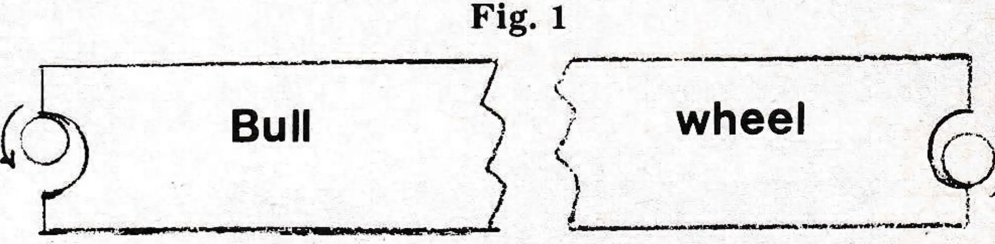
How about the entry to a bull wheel? A bull wheel provides a much greater control of the cable than the towers by reason of the greater pressure and area of contact. Assuming the groove in the liner to be well defined with a discernable bottom dead center, the bottom center is where the cable will roll to. It can be seen then, that if the guide sheave is set high, the cable will make first contact with the upper side of the groove and roll to the bottom; if the guide sheave is too low, it will roll upward to the bottom of the groove. Whether either case acts to hasten or retard the flow of lay depends on which direction the lift rotates—clockwise or counterclockwise. The objective is to encourage lay onto the bull wheel so, in the case of a clockwise rotating lift, the cable will enter a little above dead center. Incidentally, we are not considering any left laid ropes — only right lay.
The towers present a little different situation. Pressure is comparatively light and area of contact small. The guide sheave-bull wheel type of relationship exists, but it’s effective control possibilities are greatly reduced, the angles being confined within the limits of tower adjustments and the distance to the next tower.
There is, however, another influence often referred to as toe-in or toe-out. This could be compared to the front end adjustments on your car. On a tower we are given toe adjustments and generally camber adjustments. Caster adjustments are obviously not needed. The cable becomes the highway. In this context, toe-in should be regarded as having greater control possibilities than the groove bottoming proposition.
When adjusting to “mis-align” an effort should be made to keep the No. 1 sheaves (the one facing the oncoming cable) in a line parallel to the center line of the lift. The remaining sheaves in the battery can angle off an inch or two.
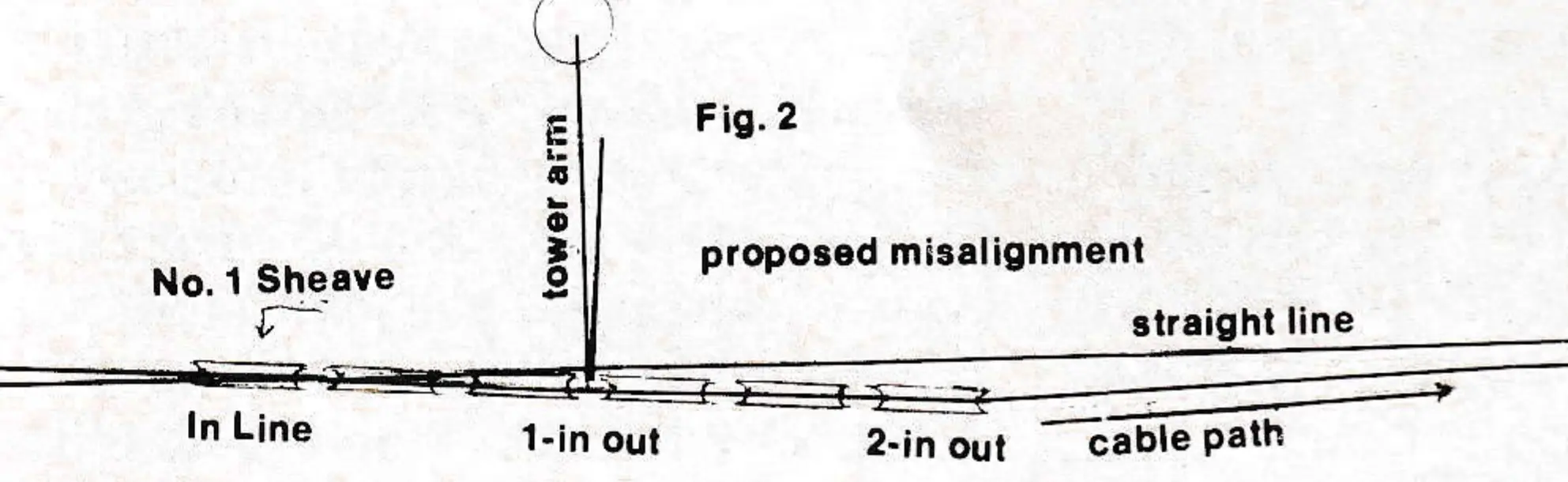
The illustration is, of course, greatly exaggerated. Result of this type of mis-alignment will be to cause the rope to rotate in a C.C.W. direction as observed in the direction of travel and toward sheave No. 1 This condition will have the effect of encouraging the flow of lay across this support tower. (Right lay rope)
It is only the ‘toed out’ condition of sheave No. 1 that serves to accomplish the purpose. Sheaves 2,3,4, and 5 continue only to serve their intended purpose; that is to support the load. Sheave No. 6 suffers a little in that the cable will hug the inside of the groove as it departs toward the next tower.
CAUTION: Don’t overdo this. The one inch -two inch departure from the straight line is about as far as you should ever take it.
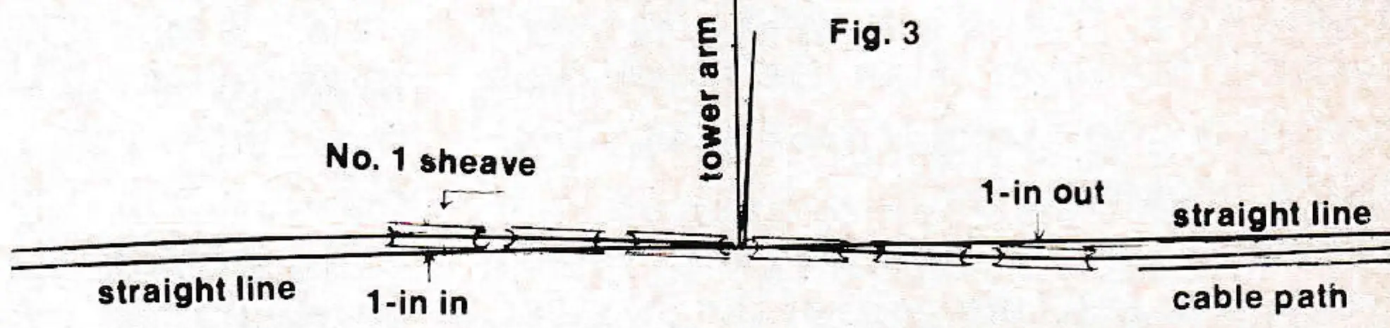
We changed Fig. 2 by angling the entire assembly about the center which is supposed to be on the straight line. The 2 inch jog is still there. Two inches is about all the jog we want. The difference is that we lost half of the toe out we had in Fig. 2, but we gained a little of the “roll to the bottom” effect we talked about in connection with the bull wheels. I can’t honestly say that one of these methods is better than the other. It’s a pretty sure thing though, that method ‘2’ will be used simply because it’s so much easier to do.
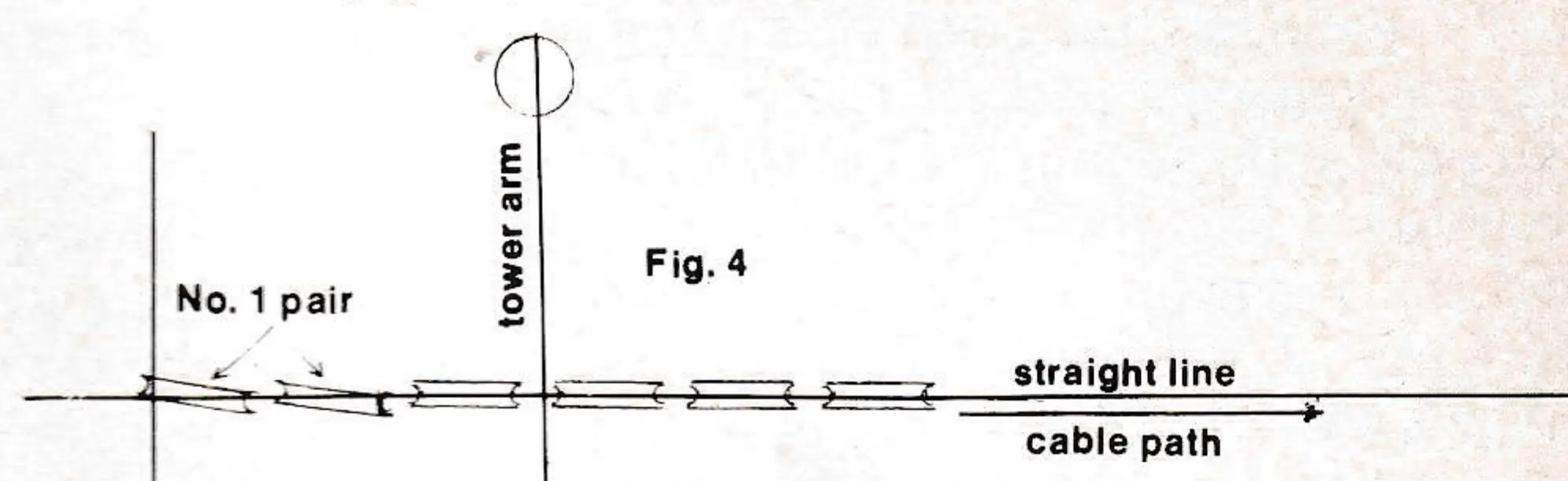
Sheaves 1 and 2 are angled on their own axis. The balance of the sheaves remain in a straight line. This situation has, to date, not been seen by the writer, but I have long thought it just might work. Any body willing to try it?