


It is the intent of this article to explore these specific questions. The answers are of crucial importance to the owner-operator of any lift to be able to reap the desired service from the lift. The subject will be examined from the basic code requirements on up.
In the United States, the minimum basic design requirements for a chairlift safety system are generally adopted from the ANSI B-77-1 Standard Safety Requirements for Aerial Passenger Tramways. We therefore turn to this standard for a definition of the “safety control circuit” for any lift. Alas, we find that there is, in fact, no such animal as the frequently called “safety circuit;” there are, however, close cousins. The 1978 addendum to the standard has, for the first time, seen fit to define the “Electrical Control Circuits” for lifts and tramways. Two alternate circuits are now officially defined under the new Section 1.8.12, as the “Emergency Stop Circuit” and the “operating control circuit.” The “Emergency Stop Circuit” is thus defined as “an electrical control circuit that when interrupted will automatically cut the motive power and apply breaking to stop the tramway . . .” The operating control circuit is defined as an “electrical control circuit that governs starting, speed and normal stopping of the tramway.” Although not clearly delineated in the Standard, the “operating control circuit” is basically the “manual” control circuit as defined in Section 2.1.9.5, stipulating that on any lift which has only a simple stop circuit, such circuit shall be classified as the “emergency stop circuit.” This discussion will therefore concentrate on the problems/solutions related to the “emergency stop circuit,” as the chairlift safety circuit is now officially referred to, although many aspects of the subject may also apply to the so-called “operating control circuit.”
The criteria which the Standard stipulates for the electric stop circuits are stated in section 2.1.9.5 and comprise only the following requirements;
- Circuits must be of the energized type so that in the event of electric power failure the system shall fail safe and the lift shall be inoperative;
- Circuits must be all metallic
- Inadvertent ground in the circuit shall cause the system to fail safe;
- Interruption of the emergency stop circuit shall stop the prime mover or auxiliary prime mover, whichever is in use.
The stipulation of “energized type” implies that the circuit be interrupted (and lift stopped) not only by a tripped switch or wire breakage but also by short circuit. It implies that all switches in the lift electric stop circuit must be closed when the lift is in the operational mode, and that the opening of any one switch will cause the lift to stop.
The capabilities that the electric control circuits must provide for a chairlift are defined in Section 2.2.11.2 and 2.3.3.1.2. These require that the chairlift prime mover be stopped automatically and that the service brake be applied in case of the occurance of any of the following events:
- passenger traveling on lift beyond any unloading area (except intermediate unloading);
- if rope leaves bullwheel or departs from its normal running position at the bull wheel;
- if the counterweight or tension sheave carriage reach either end of their respective travel;
- in case of deropement from any tower sheave unit;
- in the event any manual stop station is activated.
The Standard however makes no stipulations as to how the foregoing requirements are to be accomplished. Obviously, to achieve thse capabilities, circuit interruption switches are required at each indicated function sensing locations.
Translating these stated and implied requirements into practice, indicates that, depending on a particular designer’s preference, at least 10 to 15 switch locations are involved in the terminal areas plus two switches per tower. For the average 20 tower lift this amounts to over 50 separate switches. As each switch has at least two terminals and each pair of switches is interconnected by at least one wire, 50 switches would translate into 200 possible connections which become potential problem locations. In practice, however, switches are normally wired to terminal blocks which interconnect the wiring, so that, realistically some 300 or more potential problem locations are created. Each connection is a potential future problem.

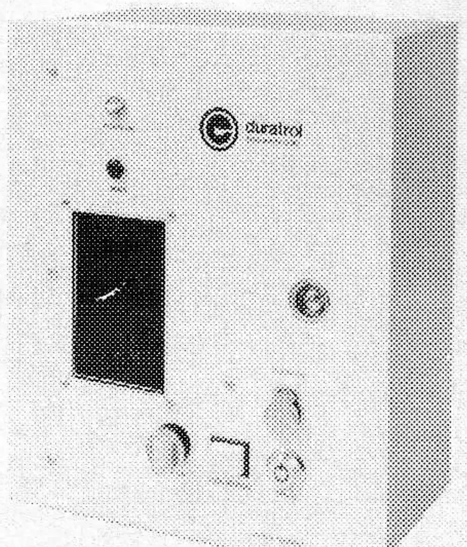
The cause for this is better understood when one realizes that the various circuit components are not favorably influenced by typical chairlift environments. (Conditions such as severe temperature cycling, moisture, vibration and, in some coastal locations, corrosive atmospheric conditions, all affect their reliability.) Thus, to obtain lthe safety protection benefit of the prescribed switches, many potential circuit integrity problems are introduced.
The economic realities of the operation of the chairlift as a business require not only that the lift be operating safely without possibility of harm to passengers, but also that the lift stoppages, regardless if they be of the preventive safety type or due to other causes, be of minimum duration, Passengers do not enjoy sitting on a lift that is not moving or that stops frequently. Hence, a rapid and reliable fault locating and determining system has become an economic necessity. “Rapid” and “reliable” are key words here as the addition of any type of monitoring system inherently tends to complicate the circuitry.
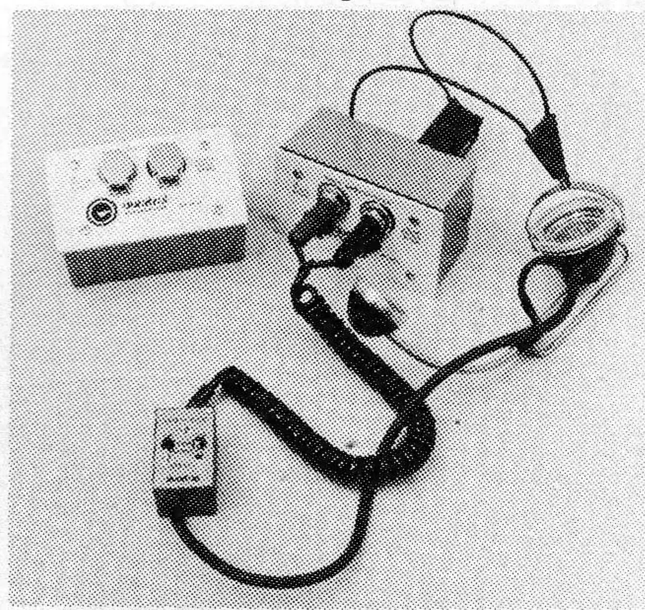
To summarize the specific properties of a reliable emergency stop system that will provide the lift’s owner/operator with information necessary to minimize the lift’s down-time, the system must (1) Have the capability to instantaneously detect, locate and legibly announce the problem which caused any particular lift stoppage; (2) Have a minimum of external wiring and components to connect the sensing switches; (3) Have monitoring capability that is both sensitive to the tripping of these switches, and also able to monitor faulty switches, intermittant or fluttering switches, and multiple problem situations. The system should be capable of reacting to wiring problems such as an open circuit — be it due to a broken wire or a loose connection — short circuit due to touching wires and grounded circuit. Indication of the location of such problem should also be provided.
Lastly, the system should have built into it a readily usable testing device to facilitate periodic checking of system integrity. The testing system should be equipped with a separate voice communication system (telephone), independent of the lift telephone system, capable of providing communication from each switch location (tower or terminal) for testing or for trouble shooting.
Jurisdictional authorities or insurance interests — to say lnothing of common sense — mandate that the owner/operator of a lift comply with the “emergency stop circuit” provisions stipulated in the Standard. Judicious economic considerations of coping with the real world remifications of the stop circuitory system, point to the equipping of the system with the type of reliable monitoring and trouble shooting capability as described.