


The use of a simple, normally closed, fail-safe circuit — even when used with fail-safe switches, automatic unintentional ground detection and shutdown device — cannot be considered as offering an acceptable level of safety. True, even when tested regularly as per ANSI B77 standards.
This is because a simple ground fault can allow a current leakage that is capable of jumping one or more switches and of keeping an ordinary relay closed. (Due to construction, there is a difference between closing and opening voltage that cannot be ignored — as between 2.5 and 25 volts, for instance, or 1:10!)
Analyzing a Common Occurrence
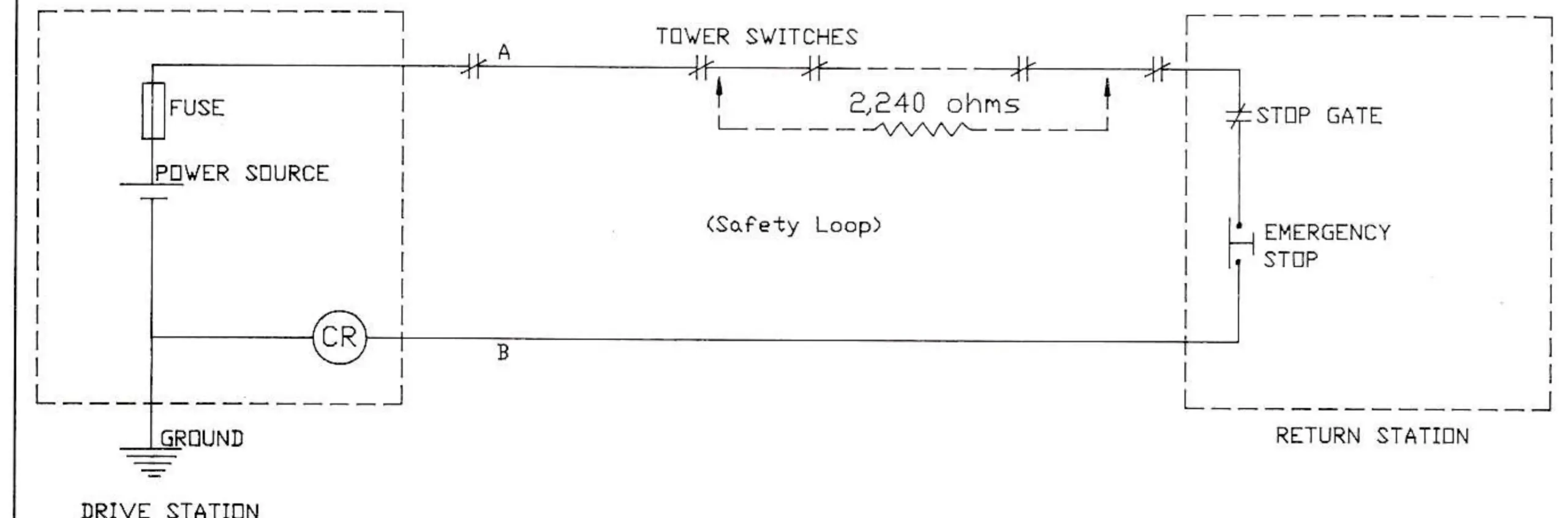
Consider an ordinary relay, CR, with a winding resistance of 250 ohms, powered at 25 volts and which opens at 2.5 volts.
Even if the resistance between lines A and B is infinite, a fault of 2,240 ohms at the terminal of one or several switches makes it inoperable. When they open, the relay stays closed.
Such a fault is possible, but unlikely at the level of the safety switches themselves.
If, on the other hand (Diagram 2), the resistance between lines A and B drops to 2,260 ohms (humidity, water, corrosion, lightning-caused arcing), even a slight fault of 250,000 ohms at the contact terminals is enough to make it useless! This type of fault is common enough and seems to have the nasty tendency to arrive at awkward moments.
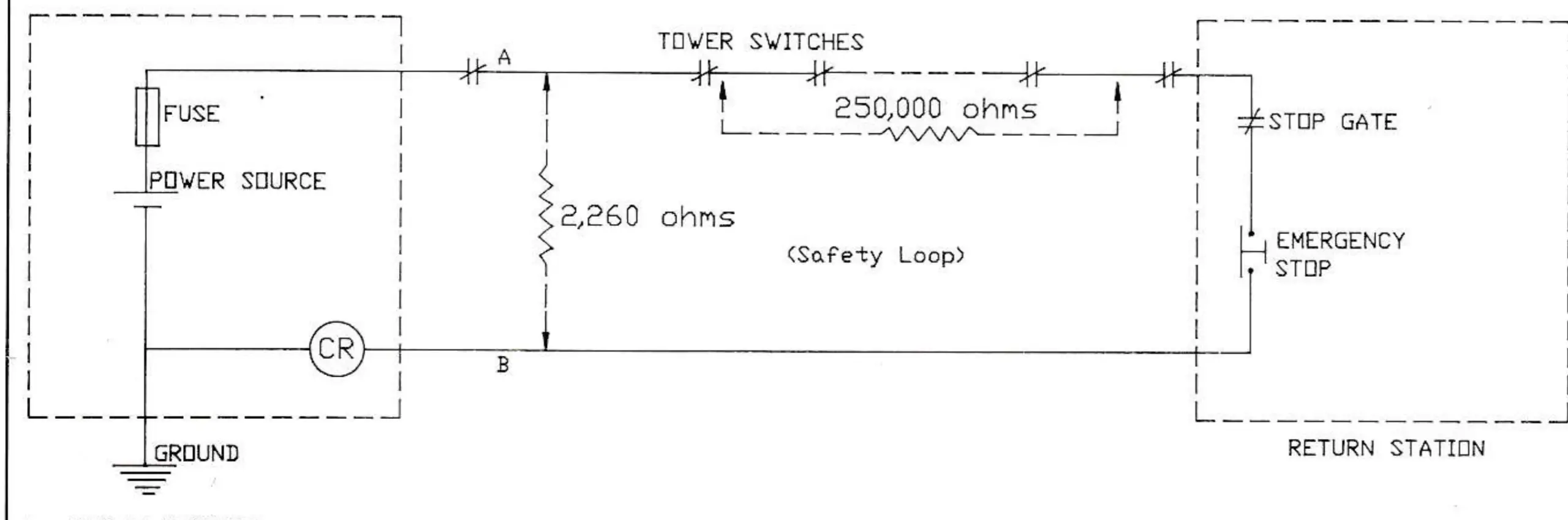
At any moment, bad luck may bring the values of these two resistances to infinity—with, often, the same alarming result. In these cases, obviously, the emergency stop button at the return station functions normally and thus prevents the anomaly from being detected!
What’s more, if the general ground bonding has deteriorated, the risks are considerably increased and other breakdowns, possibly more complex and just as difficult to find, are foreseeable.
Insulation faults are often random in nature — resulting, as they do, from such factors as humidity, temperature, age of insulation, etc. — and a normal daily operational test cannot give a 100 percent guarantee of its ability to halt the system. This applies equally to automatic and manual equipment.
In these conditions, a simple relay cannot be considered adequate!
Finally, both the environment and usage of the system are significant in evaluating the possibility of an emergency stop being ignored — factors such as line length, exposure to bad weather, lightning, long periods of disuse, maintenance levels, operator competence, etc.
The fundamental role of a safety loop monitor is to continually check on the state of the line which should control it, while at the same time assuring that the monitor itself has no fault or breakdown — even of a single component — which could stop or hinder it from fulfilling its function.

The safety loop monitor plays other roles as well — not just for the sake of keeping the show rolling, but roles which further enhance safety:
- Indicates the nature of the fault on the line so as to facilitate repairs;
- Localizes the point where a switch (derailment switch, stop gate, stop button etc.) was activated so as to speed up the restarting of the machinery;
- Accepts any fault which cannot impair its operation (but still indicates them so that preventive maintenance can be carried out);
- Assures that the safety circuit lines — usually on their own installed towers — are not in an abnormal state due to wind, frost, oscillations or mechanical breakdown that could cause an incident.
Certain monitors allow the following:
- Insertion of indication repeaters along the length of the line (return station, intermediate stations);
- Automatic checking of the continuity and grounding of the common bonding conductor along the length of the lift;
- Evaluation of the insulation value on the safety wire;
- Detection of the inadvertent grounding of the return wire, if this is insulated.
Another problem which the safety loop monitor must handle is that of its own protection against lightning and atmospheric discharges which, by their very nature, are associated with the use of long lines. This is especially so in the mountains, on top of huge masses of rock and metal, which act as excellent lightning conductors.
In order to resolve this problem there is a wide range of accessories available, of varying efficiency. Here, the experience of the manufacturer is important. Ferrite fuses represent one of the most effective and modern protection elements known.
These, then, are the goals of what we call a safety loop monitor. It enjoys wide acceptance today and, indeed, its use is called for in most applicable standards and regulations. In some countries it is required by law that they be manufactured in compliance with ISO Quality Assurance Standard 9001.
The advantages and disadvantages of the different principles adopted by various manufacturers will not be dealt with here. Ultimately, it is the experience of the user which will guide the choice between the different models available. Each user will have his own priorities, based on the harshness of the environment affecting his lift operations, and these criteria will automatically establish the criteria of choice: reliability, lightning protection, simplicity of use etc.
The concept of the “fail-safe ground circuit” — considered sufficient in all but a few cases, assuming the circuits are correctly housed and protected (cabinet, building) — has undergone continuous evolution in the lift industry; the safety loop monitor responds to these new requirements. Nonetheless, simply installing a good safety loop monitor is not enough to obtain a good remote-controlled emergency stop. It should be thought of as a link in the chain which ends with the cutting of the power and the application of the mechanical brakes.
For the harried lift operations manager, these devices may sometimes seem only to hinder the smooth running of the operation—or worse, to be expensive, useless gadgets! In fact, as the guarantors of a subtle, vital function, they are his friend.