



Water hydrants used in snowmaking are essentially freeze-proof versions of commercially available angle-globe valves. Hydrants in most snowmaking systems will be hard-pressed to have more than 100 hours of use per season. But, while hydrants may have relatively few hours of use per season, those hours are often spent at extremely high pressures and flow velocities. In addition, hydrants are exposed to the elements year-round, which can result in corrosion, freeze-thaw cycles and drying of seals and packings.
This means that water hydrants intended for long life should be built of rugged, corrosion-resistant materials, engineered for relatively brief, high-pressure periods and for seasonal-use flow.
Because there are a number of snowmaking hydrants available that use varied construction practices and make various claims, selection may not be as simple as shopping for the lowest price.
Pressure Ratings
The first step in evaluating hydrants is to determine the maximum operating pressure of the water pipeline at the hydrant location and at the snow gun after hydrant throttling. With fan-type guns, pressure at the gun will be the pipeline pressure minus the pressure drop through the hydrant in the full-open position.
Pressure rating claims of most manufacturers (1,000 to 2,000 psi) are valid for the hydrant inlet housing only. But the weakest links in the chain are the outlet quick-connect fittings and the snowmaking hoses, which are available up to 750 and 800 psi respectively. Such high pressures at the gun, however, are typically seen with fan guns and the new high-efficiency tower guns. Water hydrant inlet and outlet pressure ratings are most critical when using these guns so the use of schedule-40 steel pipe for the hydrant main riser at such high pressures is questionable. Problems may manifest themselves as the hydrants corrode, especially at the exposed pipe threads, resulting in a potential safety hazard. Heavier schedule-80 pipe would be a better choice for long life and personnel safety at high water pressures.
Size Selection
Water hydrants are available with riser pipes from 1-1/2 to 2-1/2 inches in diameter, with the 2-inch size being the most common. But the nominal hydrant pipe size does not necessarily dictate the proper hydrant for the type of guns being used. In the final analysis, the optimum hydrant size for a system depends on the type of snow guns being used.
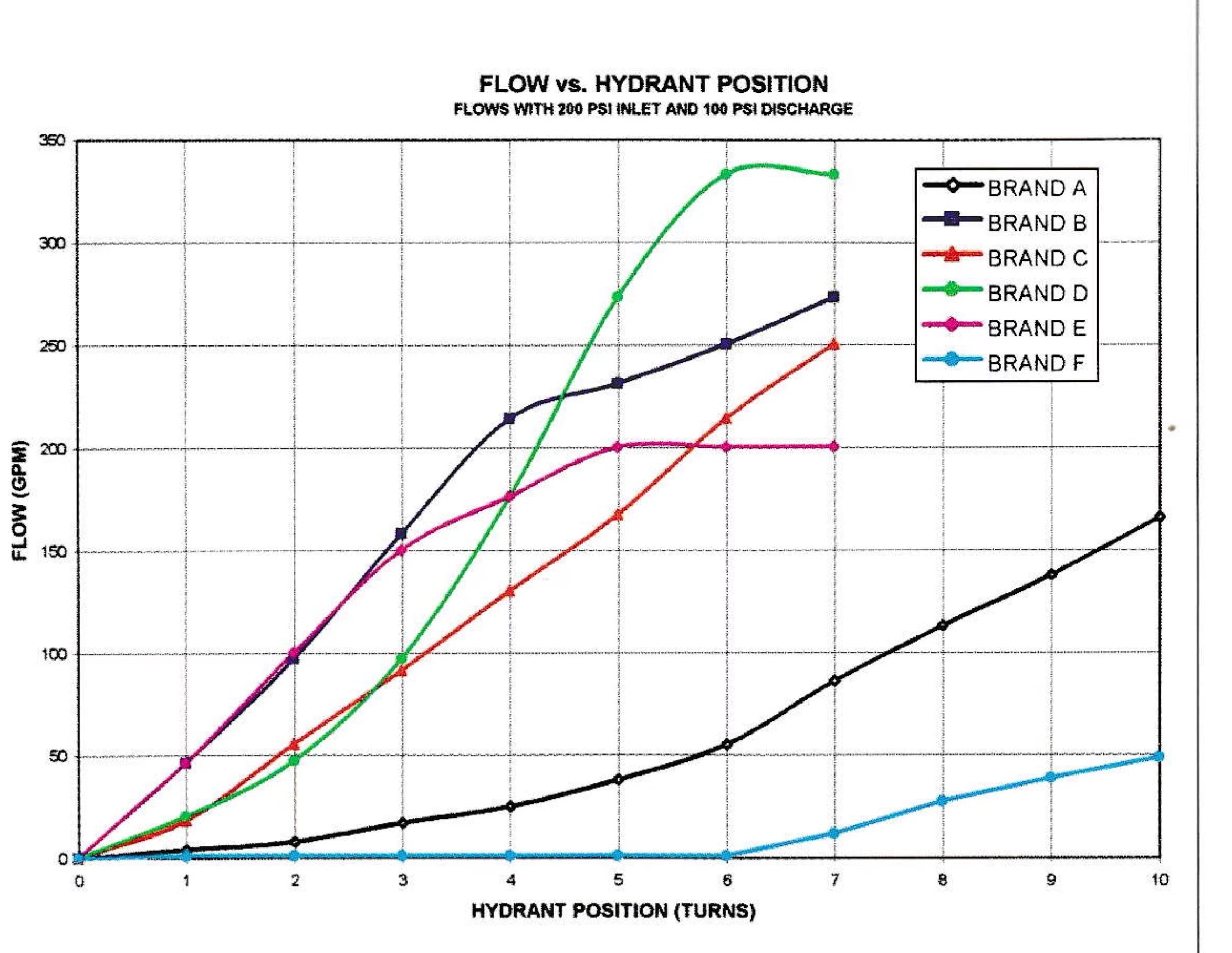
On the other hand, flow characteristics vary widely by manufacturer, even for the same size hydrant. The accompanying graph shows test results of the flow characteristics of six commercially available two-inch hydrants with 200 psi inlet pressure and 100 psi outlet pressure. As can be seen, for this inlet/outlet pressure combination, Brands A and F are suitable only for small capacity guns, while Brands B, C, D and E are suitable for the majority of commercially available snowmaking guns.
For fine water-flow throttling, a hydrant that would produce a shallow curve in this test is desirable because it indicates that flow can be increased at a moderate and controllable level with each turn. For consistent flow increases per turn, a more linear curve is desirable, which indicates that water flow is raised by a consistent amount for each hydrant turn regardless of position.
Test results also indicate that Brand D is more difficult to adjust than the other models due to its varying and steep flow curve. A single turn resulted in as little as 10 GPM flow change to as much as 100 GPM flow change. On the other hand, Brand C resulted in a consistent increase of approximately 40 GPM per hydrant turn throughout its range. Brands A and F required many turns to reach a desired flow level, which hampered adjustments. With some hydrants, manual adjustment was somewhat tricky, while hydrant automation could be impossible without water-flow or pressure feedback devices.
With respect to air hydrants, most systems use two-inch diameter ball valves. Use of 1-1/2-inch ball valves is not recommended due to excessive pressure drop through the valve, which could reduce efficiency. If a 1-1/2-inch ball valve must be used, it is suggested that a full-port style with larger air passage be specified. Constricted air hydrant passages will lead to pressure losses and a resultant loss in snow gun efficiency.
Construction Methods
Water hydrant construction varies widely between manufacturers. Many water hydrants, such as those made by Larchmont, Rogers and the Ratnik C Series, utilize a plug made of plastic (acetal) to provide flow control and shut-off. Although they are inexpensive and tolerate minor scratches, plastic plugs rely on O-rings to provide positive sealing, which could be a potential maintenance issue. Metal-to-metal seating surfaces, like those from HTM and Ratnik, are more expensive to manufacture, but tend to be more resistant to wear, especially if the surfaces are hardened stainless steel.
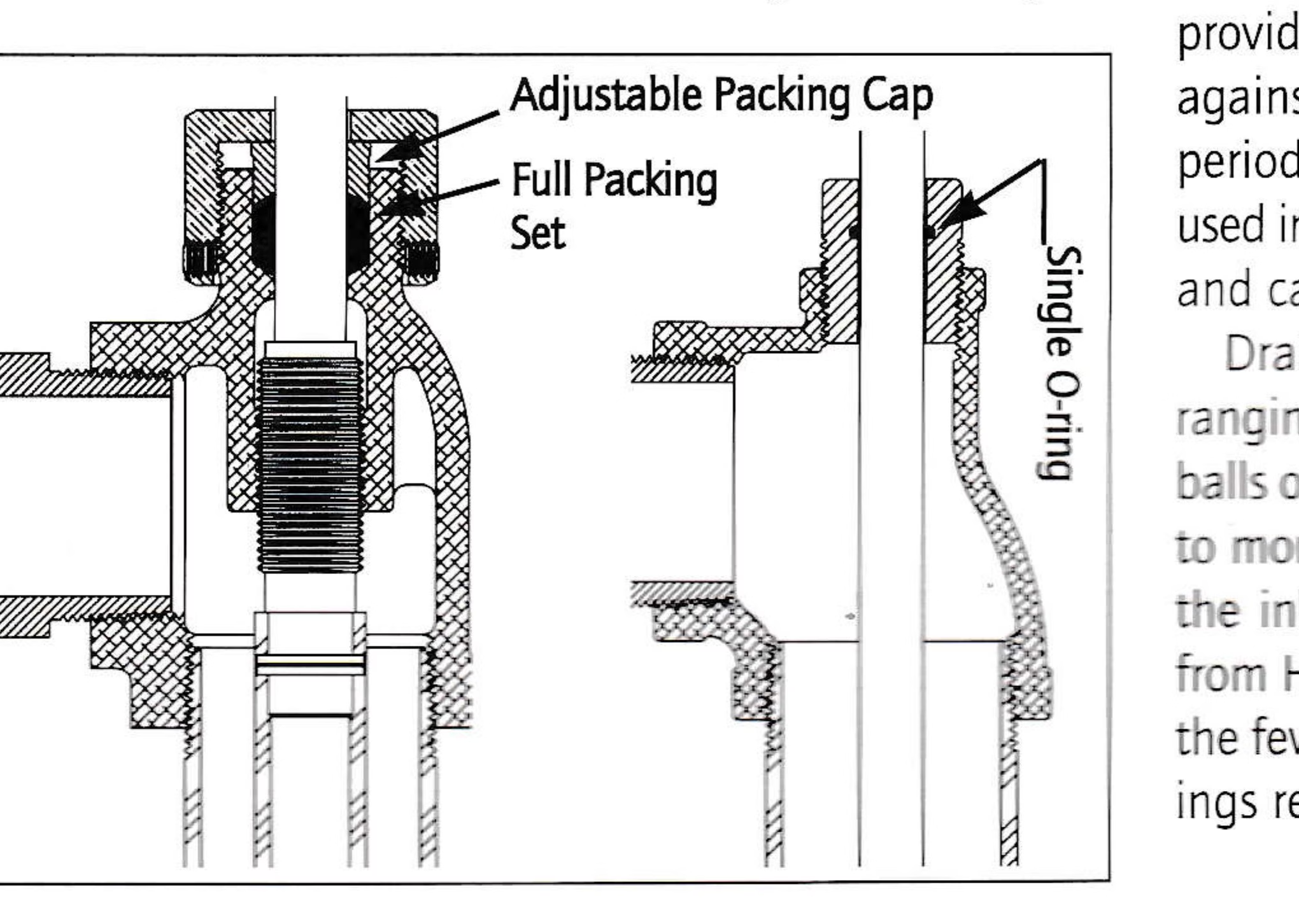
Most manufacturers provide a full valve-stem packing, which is standard practice to prevent water leakage from the shaft. One exception is Larchmont which uses a single O-ring. Full packings provide a longer lasting, reliable seal against high pressure, but also require periodic tightening. Packing materials used in water hydrants include teflon, flax and carbon yarn.
Drain-valve styles vary widely as well, ranging from simple spring actuated balls or plungers—found in most valves—to more complex drains integrated into the inlet housing, such as the hydrant from HTM. In general, drain valves with the fewest moving parts and large openings resist freezing and clogging.
Installation Procedures
Improperly installed hydrants can become major headaches when starting to make snow, because internal parts or the hydrant stand pipe can freeze or crack. But there are basic procedures and techniques that can help avoid common installation errors.
In freeze-proof (deep-bury) installations, be sure to provide a proper gravel bed around the drain, at least two cubic feet, and more for clay or low permeable soils. Place a polyethylene sheet or landscaping cloth over the bed so the surrounding soil will not fill cavities in the gravel bed. If an inadequate gravel bed is installed, water cannot seep into the surrounding soil, but it will remain in the hydrant with the potential for freezing in the future.
In above-ground installations, be sure that the drain valve is not pointing uphill. This could allow a small quantity of water to remain in the hydrant, making the hydrant difficult or impossible to open.

Water hydrants with a female pipe-thread inlet should be installed to the pipeline with schedule-80 nipples. The extra wall thickness will provide for some corrosion and a safer installation, while costing very little extra.
Reexamination Time
Water hydrants are designed to be fairly simple devices that have the reliability required in snowmaking operations. Improperly selected or installed hydrants can result in adjustment difficulties, loss of efficiency and damage as well as potential safety hazards. For these reasons, hydrants should not be specified strictly on price.
In addition, materials used in construction and hydrant performance characteristics can vary widely between manufacturers. Even the best materials mated with a complex design can be detrimental from a maintenance standpoint. It’s never too late to examine how hydrants were specified and installed to see what potential improvements might be made. Careful examination reveals that not all hydrants are created equal.
Hydrants may not be the most glamorous features in a snowmaking system, but careful and intelligent selection along with proper installation can make them seem downright sexy.
Hydrant Test Procedure
When evaluating flow capacities of hydrants, three characteristics must be known: pressure drop across the hydrant, amount the hydrant is opened (turns or displacement) and the flow rate (GPM) for that condition. Flow will vary continuously as inlet and discharge pressures vary and as the hydrant is adjusted.
When considering all of these variables, it is difficult to compare hydrant flow performance data between manufacturers. However, one characteristic that remains constant for any hydrant regardless of inlet/discharge conditions is the valve coefficient, or Cv, which varies only when the hydrant is adjusted.
Knowing the hydrant Cv, a flow rate can be calculated for any pressure.
Flow = Cv x √ΔP
Where: Cv is the valve coefficient; Flow is in gallons per minute (GPM); ΔP is the pressure drop (inlet pressure-outlet pressure)
Flow testing for this article was performed on February 3, 1997 to determine the flow characteristics of six commercially available two inch water hydrants under controlled conditions. An electronic differential pressure sensor was used to monitor pressure drop and an electronic vortex flow meter was used to monitor flow. Both instruments were either new or recently calibrated by the manufacturer to be +/- 1 percent accurate or better.
Each hydrant was instrumented and water flowed through them. From a fully closed position, each hydrant was opened incrementally, one turn at a time, while pressure drop and flow were recorded.
A Cv versus hydrant position chart was then plotted for each hydrant. The chart shows a comparison between the six hydrants under identical conditions (100 PSI pressure drop). As can be seen, flow characteristics can vary widely, even under identical conditions.
Hydrant Models Tested
- Ratnik Model 2000
- Ratnik Model 200C
- Larchmont W2000
- Rogers 2 inch
- HTM Hydrotech 2 inch
- Delta 2 inch
All hydrants were nominal 2 inches diameter and 6 feet-0 inches length as measured from the bottom of the hydrant to the centerline of the outlet fitting.