


1. The Science (and Art) of Splicing Six-Strand Wire Rope
The process of performing any task may be broken down into two parts; the science and the art. The science is the basic understanding of how to perform the task and the logical reasoning of why that method is correct.
The art of the task is the skill which is acquired by many years of practice where the technique of the task is developed and perfected.
For many years, there have been many opinions of how a splice should be done and just as many opinions why. Although a typical splice contains only 6 tucks with 12 strands, it is difficult to understand what is happening when the rope is in its closed helix form. The diagrams which follow show the splice opened up so that the individual strands are identifiable.
There are two premises which are generally agreed upon, though I have never seen them in print: 1. The splice achieves its strength by the opposing or interstrand contact; and 2. The tuck or tuck marriage is a method of getting the tails of the tuck out of the way and perform no function of increasing strength.
With these two premises, what then determines the strength of the splice? It should be evident that the increased length of the splice will increase its strength up to some point. It should also be apparent that the balancing of the interstrand contact on all 6 strands would also enhance splice strength.
An effort was made to see just how the layup of the splice affected the interstrand contact. Although over 14 configurations were reviewed, three basic splice marriage configurations will be shown here to demonstrate their various qualities.
Why are the tucks staggered? This is necessary since the tuck ends (that portion of the strand which is tucked into the rope, replacing the core), can not exist at the same place. If we accept the two basic premises, the length of the strand which is tucked beyond the tuck marriage is unimportant as far as strength is concerned. At the tuck marriage, there are seven strands and no core. Once the tail replaces the core, we have six strands and a strand core, whereas at most other places, we have six strands and a core (usually fiber).
A review of the relative stiffness of the rope finds the most rigid point at the tuck marriage. The next most rigid part of the rope is where the tail has replaced the core. Finally, we reach the point where only the 6 strands and fiber core remain.
It would be reasonable to expect that fatigue, which is the major enemy of aerial tramway ropes, would concentrate its effects at the point where the rope is the stiffest, which is the tuck marriage. The slight enlargement at the tuck marriage also adds to the localized stress concentration.
If the tucked ends of the strand were run end to end, a localized point of no core would exist adjacent to places of 6 strands and strand core. This would be a localized stress point which could be softened by insuring that a section of core exists between all tuck ends.
As can be seen in the enclosed sketches, the 1/1 configuration offers the best balance and greatest amount of opposing interstrand contact.
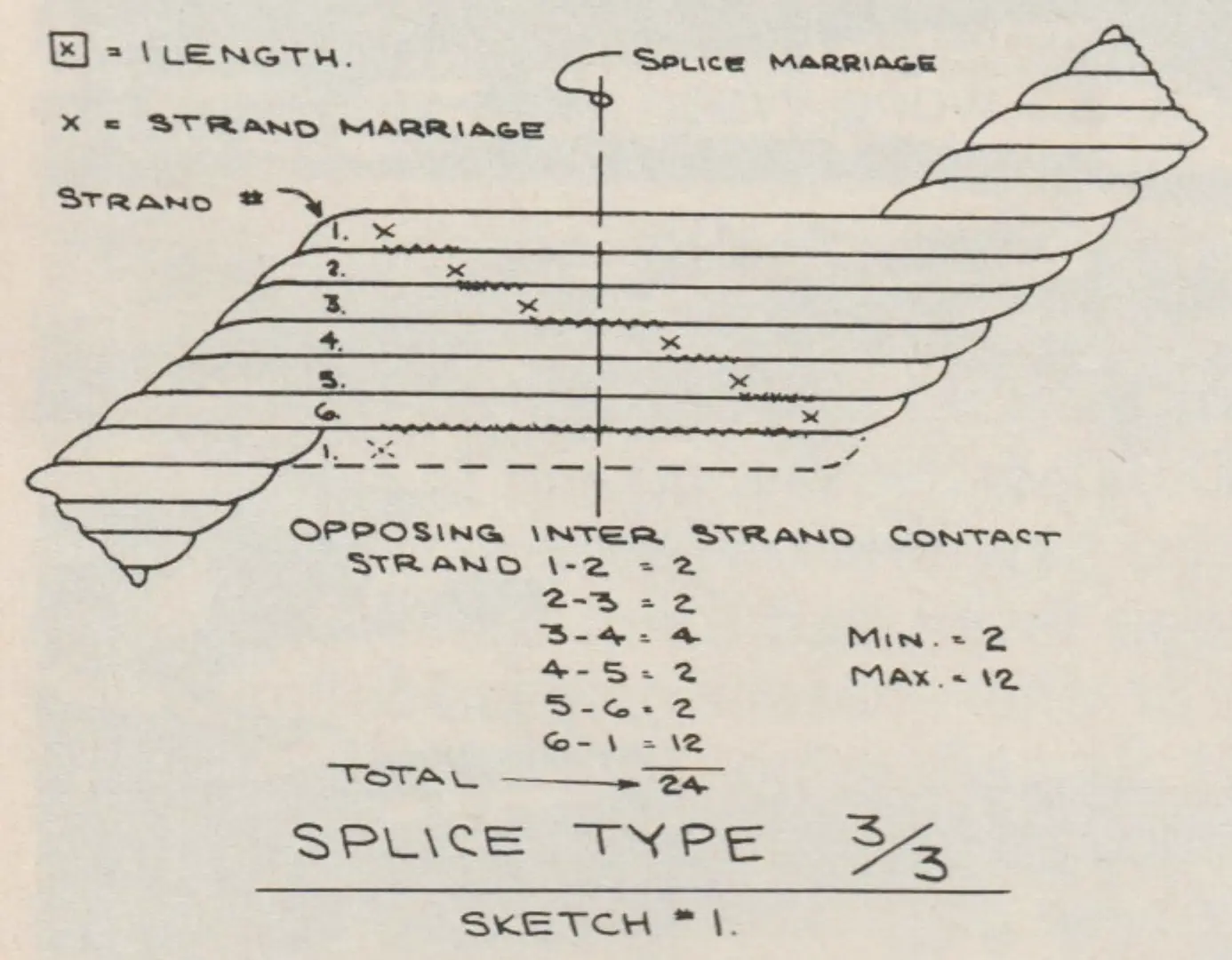
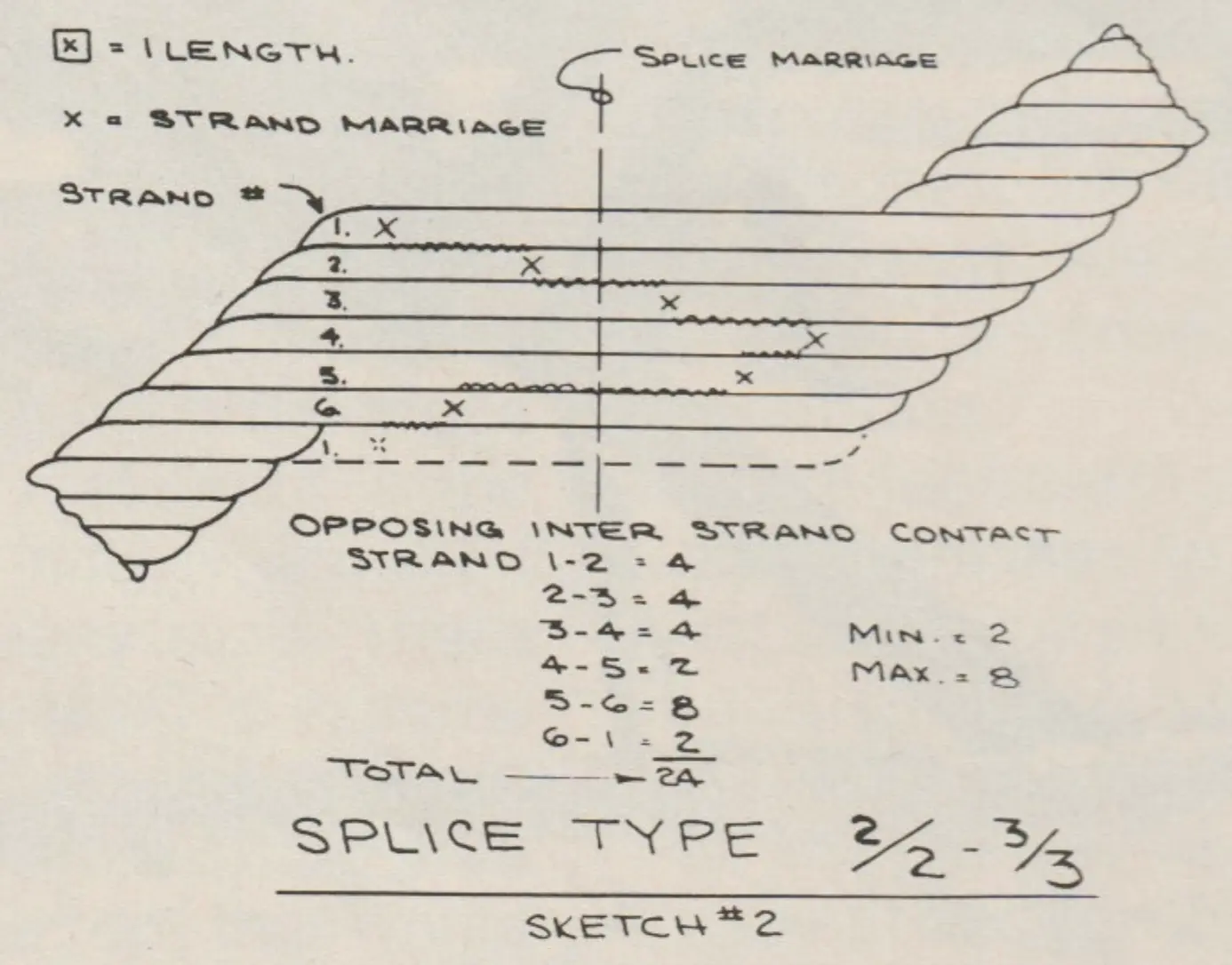
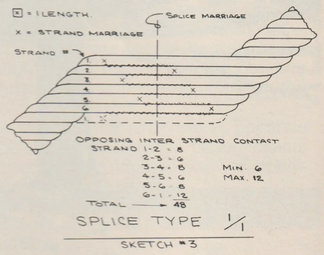
The length of the splice is defined by the ANSI B77 code as 1200 times the diameter, which is a minimum length. Providing a longer splice has a number of assets; 1. The shortening of the rope is much easier. 2. The length of interstrand friction is increased which does not add necessarily to the strength; however, it certainly adds to the stability.
Conventional wire rope splicing handbooks show splice length to be a minimum of about 384 times the rope diameter, (Ref: Bethlehem booklet #2212—”Splicing Wire Rope”). Time has proven this length to be adequate for strength; however, where fatigue is the major cause of rope replacement, the lift industry has seen fit to extend the splice length as shown above.
The owner-operator will get a much longer life out of his splice if he keeps all of his sheaves in alignment. Sheaves not in the plane of the bend of the rope cause the rope to twist. This constant twisting can flex the splice and has been known to cause premature problems.

In conclusion: 1. The best splice configuration is the 1/1 with the 3 tucks on each end of the splice close together. 2. The longer the splice, the better it will perform. 3. Keep all sheaves in line and in the plane of the bend of the rope.
That’s the science . . . remember, there is also the art . . . The Wire Rope Splicer.
2. Some Tips on Tucks
by Dale R. Walters
Splicer, Paulsen Wire Rope Corporation
From time to time my field experiences make me wonder whether enough concern is given to the splicing procedure for main haul ropes on ski lifts and aerial tramways. A little forethought will many times save disappointment and, in some cases, money.
For instance, when the main haul rope is being readied for tensioning and tying off before splicing, be sure that the tie-off ropes are the same diameter as the haul rope, that fist grip type clips are of the correct size, and that at least the minimum number of clips are used. A right hand lay main haul rope should be tied off with right hand lay tie-off ropes and likewise with left hand lay rope.
If the ropes are right hand lay, then first grip type clips with right hand ruddles in them may be used. If, however, the ropes being tied off are left hand lay, the clips should be perfectly smooth inside unless it is possible to obtain clips with left hand ruddles. To my knowledge neither of these types of clips are readily available. However, a manufacturer of fist grip type clips has recently run tests on clips with the ruddles ground off flush. These tests have indicated the clip efficiency remained high. Therefore, fist grip type clips with the ruddles ground off may be used on both right and left hand ropes without damage to the rope. It is also important to use the correct number of clips, properly positioned and tightened to make the parallel connection between the main haul rope and the tie-off rope. The following chart lists the minimum number of clips I would use. The spacing and torque are those listed by manufacturers of fist grip type clips.
| Wire Rope Clip Size | Minimum # of Clips | Spacing of Clips | Torque in Ft. Lbs. |
|---|---|---|---|
| 3/8″ | 4 | 7 Rope Diameters | 45 |
| 1/2″ | 6 | 7 Rope Diameters | 65 |
| 9/16″ to 5/8″ | 6 | 7 Rope Diameters | 130 |
| 3/4″ | 6 | 7 Rope Diameters | 225 |
| 7/8″ | 8 | 7 Rope Diameters | 225 |
| 1″ | 10 | 7 Rope Diameters | 225 |
| 1 1/8″ | 10 | 7 Rope Diameters | 360 |
| 1 1/4″ | 12 | 7 Rope Diameters | 360 |
| 1 3/8″ to 1 1/2″ | 12 | 7 Rope Diameters | 500 |
I tighten and torque the clip nuts three times. First, when they are installed, again as soon as the counterweight starts to move and the ropes are in tension, and the third time when the pulling operation has been completed. I recommend that periodic inspections be made throughout the tensioning operation of all clipped connections to make sure there is no slippage.
It is desirable to allow a new rope to be exposed to the full counterweight tension for ten days to two weeks before splicing. Many times this is not practical and splicing must take place sooner. If this is the case, a new rope has not been under tension long enough to allow maximum constructional stretch to take place. In any case, the rope should be spliced to position the tension carriage close to its forward stops in order to provide as much take-up as possible. It is impossible to remove all of the constructional stretch from a wire rope until it is placed under load and is run around sheaves. This procedure may eliminate the need to resplice for the purpose of shortening the rope, and will certainly extend the time before resplicing becomes necessary.
The ultimate in a wire rope splice is one that is safe, smooth, and will last the entire life of the haul rope. This can rarely be achieved due to rope stretch and various wear factors—both normal and as a result of accidental occurrences. Also, some haul ropes have to be retired prematurely as a result of splices breaking down and excessive wear in these sections. ANSI B77.1 does not specify a method for building up the tails of rope strands to be tucked into the center of the rope. Some local governing bodies have set guidelines and standards for this procedure. However, the procedure for building up the strands is often a matter of the splicer’s preference and a variety of materials may be used. Some of the materials are: cotton twine, nylon twine, cotton tape, nylon tape, friction tape, copper-aluminum tubing, hemp-sisal fiber, and Swiss braid binding.
In my opinion, the most successful and dependable method and material for building up the “tuck” strands is to closely wind the proper size nylon or cotton twine around the strand before inserting into the center of the rope. Both maintain proper core diameter and resist physical deterioration. Cotton or nylon tape does not deteriorate, but getting a proper and uniform strand diameter when applying it is difficult. The same applies to hemp or sisal fiber wrapping. Copper or aluminum tubing has been used for this purpose as well, but was found to fatigue and deteriorate very rapidly, although giving correct diameter originally. The friction tape method deteriorates very rapidly. The tape flows under pressure and emerges from the strand valleys. Obtaining correct diameter when applying tape is also very questionable and may result in a rough splice condition from the outset.
The Swiss braid binding, made like a “Chinese finger grip,” is a new item on the market. It is a synthetic material made in different sizes for each haul rope diameter, which should result in maintaining correct rope diameter and be non-deteriorating. Although expensive, the longevity of the material will have to be evaluated in the field over a period of time to determine its overall potential.