

Killington began increasing water availability back in the 1960s by building a pond and diverting water from Roaring Brook, a small upland stream, to recharge the pond during winter months. Over the next 30 years, the ski area grew to 200 trails with 750 acres served by snowmaking. Another small pond that was fed from Falls Brook, another upland stream, was constructed on the resort’s Bear Mountain in 1985. A third intake and pump station was built along the Ottaqueechee River at the gondola base terminal in 1987 to help supplement water requirements. The total storage capacity of the ponds is 30 million gallons and the two streams provide 1,500 gpm of recharge during winter months.
By 1989, the limited availability of water for snowmaking forced Killington to find more water. The new source was clear: Woodward Reservoir, a 365-million-gallon man-made lake located two and a half miles from resort property along State Highway 100. The privately owned reservoir’s water level is lowered by 10 to 12 feet each winter to eliminate ice damage to shoreline docks, allowing for acceptable winter withdrawals.
In January 1996, Killington brought together a coalition of federal, state and local regulatory agencies, and various environmental groups with the sole purpose of smoothing a path toward an efficient permitting process. Partners ranged from the U.S. Army Corps of Engineers and U.S. Fish and Wildlife Service to the State of Vermont Agency of Natural Resources and the Agency of Transportation. After months of negotiation and compromise, Killington was able, with the support of these agencies, to apply for permits to get water to the resort.
The $4 million Woodward Project took 18 months of testimony and deliberation, but received a state Act 250 permit in January of 1998. The permit was appealed to the State Environmental Board and then to the Superior Court in Windsor by an individual landowner. The appeal process took two more years, but the permits were upheld and construction started in May of 2000.
Three-Step Process
The project consisted of three distinct elements. First, a siphon withdrawal system to fill a 10,500-foot-long 24-inch pipe was built. Then 25,000 feet of progressively smaller steel pipe were linked along trails to reach the existing Snowshed and Bear snowmaking ponds. And finally, a pump station was installed to move water 1,300 vertical feet uphill.
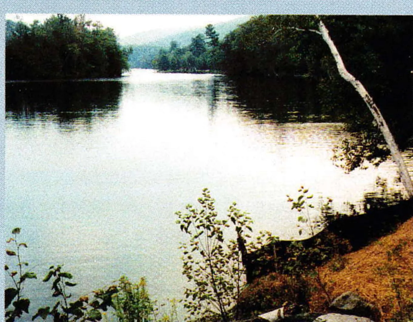
Sno.Engineering (now SE Group) designed the siphon system to fill the PVC gravity pipeline. A steel intake pipe was excavated and placed in the lake bottom in January of 1999 when the lake level was at its typical winter low point. The pump house with a vacuum pump was later located beside the reservoir at the highest point of the gravity pipeline.
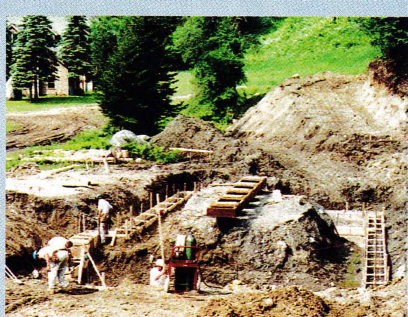
SE Group and Killington engineers laid out a pipeline route within the state highway right of way to allow for a downhill grade all the way to the project’s second element, where a vertical turbine pump station of Killington’s Northeast Passage base facility, would take over.
A block valve was placed in the 24-inch pipeline 850 feet from the pump house at a level below the bottom of the intake pipe in the reservoir. With the block valve closed, the vacuum pumps evacuate air from that first section of PVC pipeline while small water pumps fill it. When all the air is removed, the block valve is opened and a siphon effect takes over, filling the remaining 9,650 feet of pipe with water.
But the pipeline construction along Route 100 presented many challenges for Killington staff. As we excavated, all the material was removed, trucked to a nearby pit and screened to a minimum of three inches before being reinstated as backfill. A trench was dug to between seven and eight feet deep and all work took place within a trench box. An eight-inch base of gravel was laid and the 24-inch bell-and-spigot type PVC pipe (using rubber gaskets) was pushed together after meticulously cleaning each end. The grade was confirmed with a laser transit. We backfilled with gravel on top and around the pipe to a depth of 18 inches, compacted it and added the screened materials to the original grade.
Three different streams were crossed along the route. The permits mandated that the streams be diverted—one by pumping and two others by diversion pipes—in order to install pipeline beneath the streambed before capping it with concrete and rebuilding the streambed. All this happened without causing any redistribution of streams.
The first 3,000 feet of excavation occurred in very silty, wet ground, so the excavation had to be continuously pumped at a rate of 100 to 200 gpm. A large siltation pond was built to settle and clean this water before discharging to a nearby stream.
A full-time erosion-control team helped with stream diversion and also revegetated the site at the conclusion of every day. One lane of traffic had to be closed for 500 feet around the daily site for the duration of the project, which was completed in October, on schedule, at an average of 200 feet per day.
Drilling, Blasting and Welding
The second major element of this project was the welding and installation of the 25,000 feet of steel pipeline required to get the water uphill, along existing trails, to the Snowshed and Bear ponds. The Killington staff has a wealth of experience with this type of construction, however, this project presented some unique challenges. The pipe was large—12,000 feet of 22-inch diameter, 8,000 feet of 18-inch diameter and 5,000 feet of 16-inch diameter. Much of it would be buried, which in Vermont means drilling and blasting ledgerock. About 1,500 feet were installed within 100 feet of a condominium development and alongside an eight-inch PVC water line that feeds the development. On top of the physical challenges, the permit mandated completion by September 15.

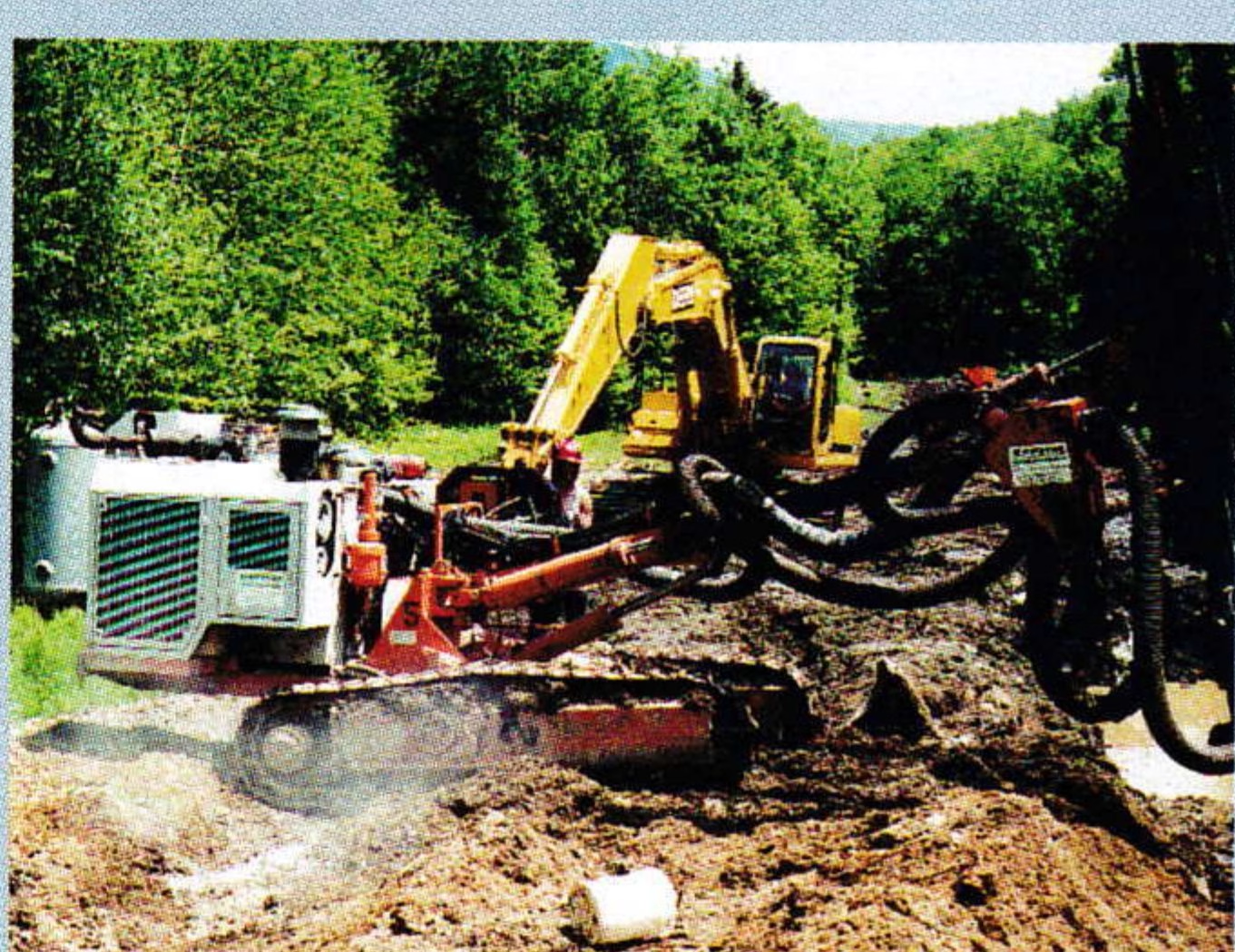
The first step was to evaluate and map the route to establish tie-in points, pipe-string lengths and excavation offset stakes. Then, construction crews had to establish erosion-control measures along the route, and weeks were spent digging water bars, staking hay bales, building construction access roads and seeding and mulching the disturbed ground. Hydraulic track drills were moved in to test for ledgerock along the buried sections in late May and blasting started where necessary.
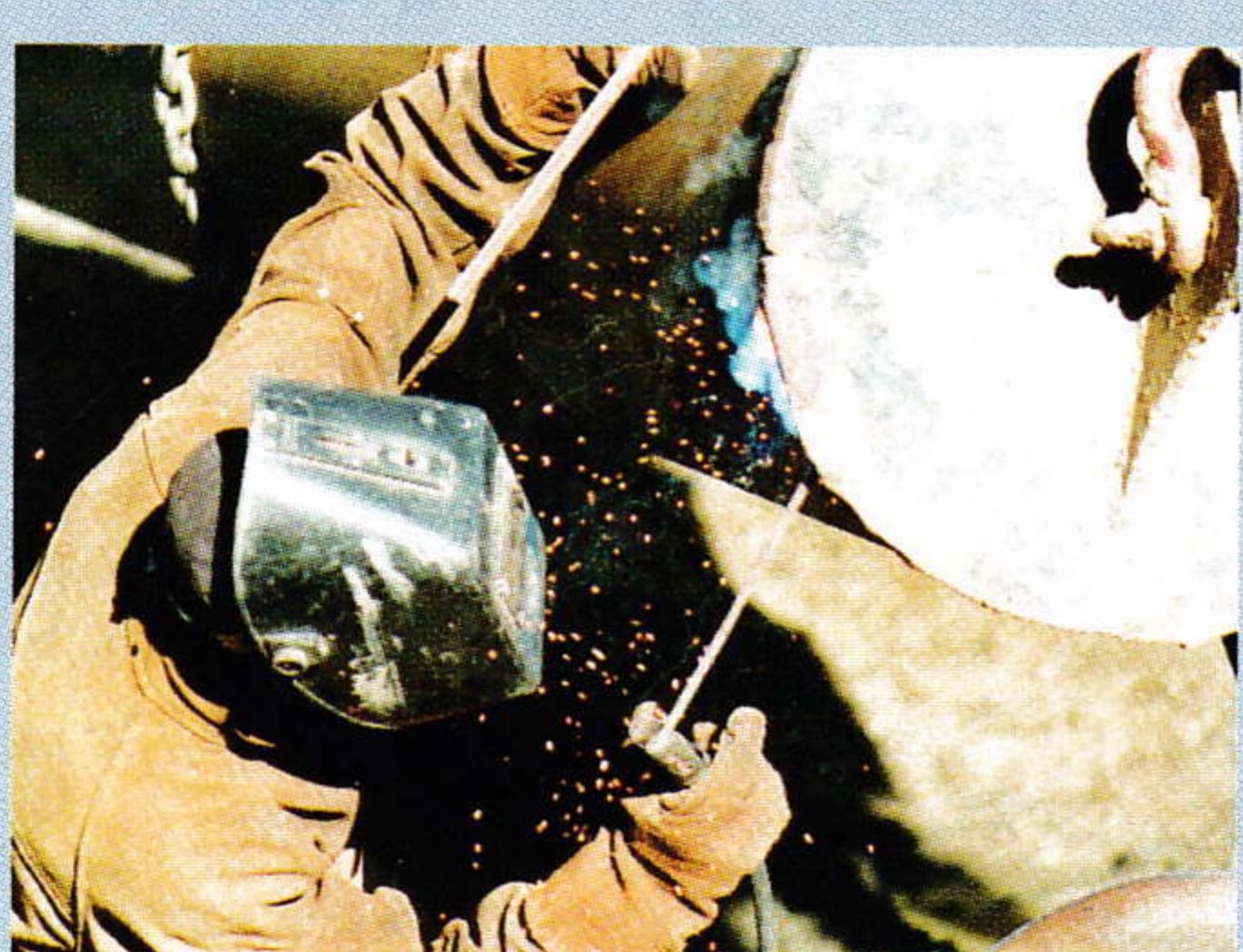
G.W. Tatro Co. was contracted to transport, string-weld and tie-in the welded sections after they were placed, either buried or above ground. Using log skidders and pipe trailers, the workers began staging the pipe in late May and welding began by early June. Multiple crews worked on different sections of the project simultaneously, along with four large excavators to dig trench, install pipe, tie the strings together and backfill. The erosion-control crew revegetated the completed areas daily.
An independent engineer was employed by the state of Vermont to oversee the specific erosion measures called for in the permit. Those inspections, as well as site inspections from the Act 250-district coordinator, resulted in high praise from all agencies for the thoroughness of the work. Organization and teamwork paid off and the mountain pipeline was successfully completed ahead of the permit deadline.
Running Water Uphill
The third element of this project was the construction of a pump station to move the new water up 1,300 vertical feet, as well as of two diversion dams to measure and ensure minimum winter flows in Falls Brook and Roaring Brook.
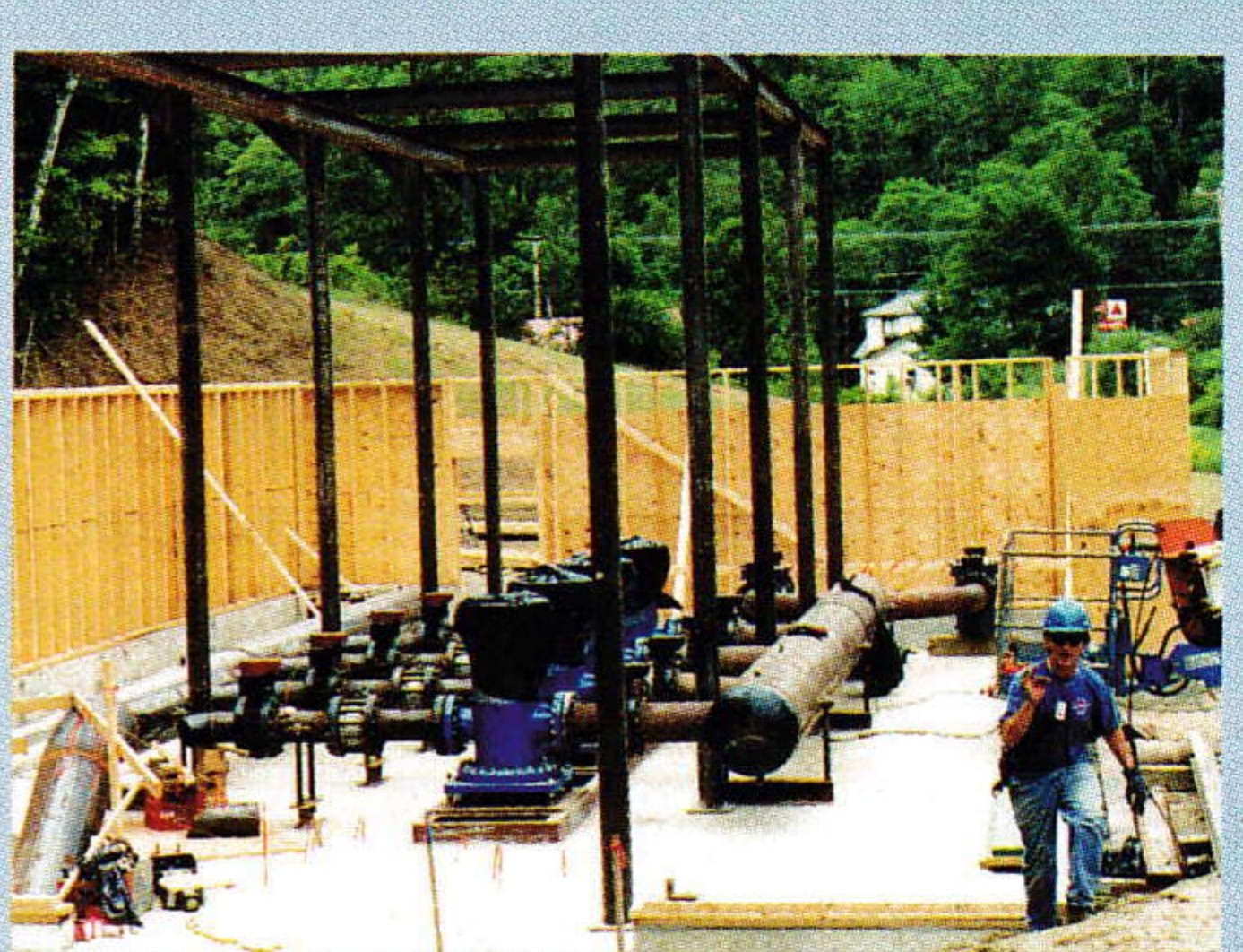
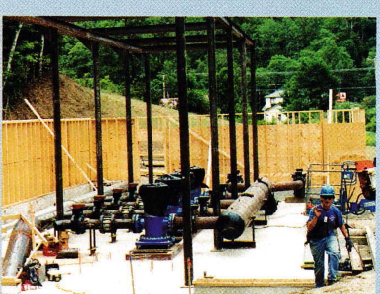
The pump station was designed by Killington’s engineering staff to pump 5,600 gpm the first season, with a final buildout of more than 10,000 gpm. Four 500 horsepower Ingersoll-Rand vertical turbine pumps and variable-frequency drives were determined to be the most energy-efficient for the job. A system was installed to allow for complete control and monitoring from the snowmaking center, eight miles away. Part of that system keeps track of the gravity pipeline, so that if a leak develops, the siphon will automatically break the cycle and drain the line. Installation went smoothly. The first pump was started on November 7, just six days beyond the target date of November 1.
The final task was the construction of concrete diversion and flow measurement structures in both Falls Brook and Roaring Brook. As part of the permit, Killington agreed to maintain the February median-flow rate downstream of the existing water withdrawal points at all times.
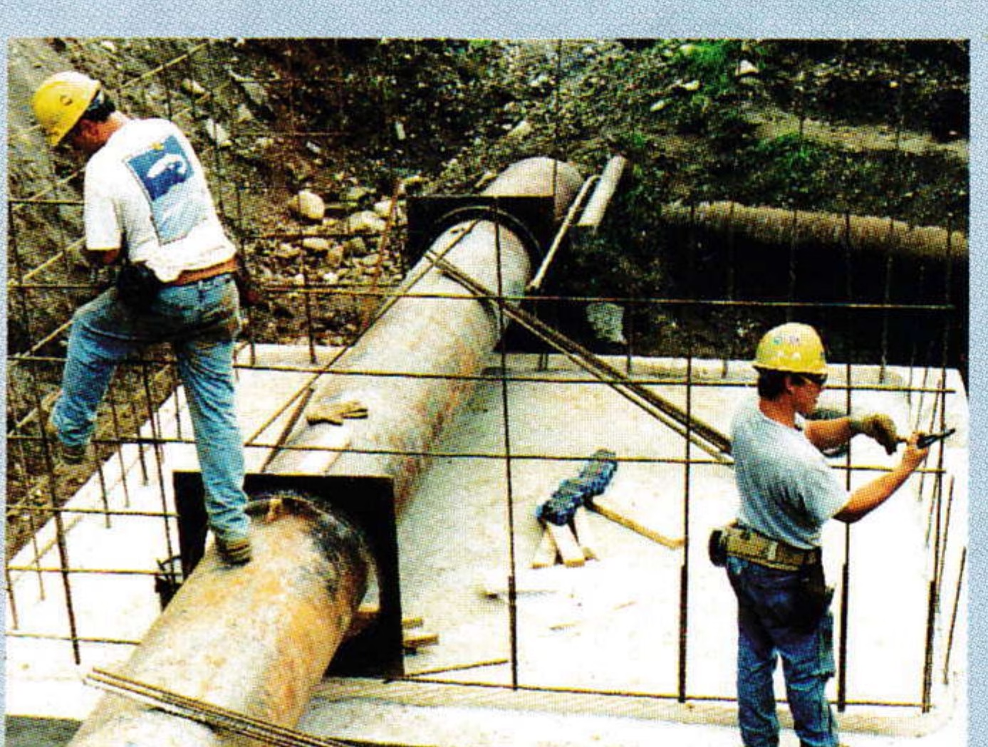
To accomplish this, SE Group designed a simple system. A concrete wall was built across the stream course with a large opening in the center to allow for normal stream flow during summer months. In November, stop logs are installed across the opening to create a small dam and the stream is diverted through a Parshal flume, which is a device calibrated to measure water flow.
To make sure water does not go to snowmaking ponds during low flows, separate concrete chambers were constructed adjacent to the streams to fill culverts that carry water to the snowmaking ponds. The chambers are separated from the streams with Weir plates calibrated to the February median flow. When the flow in the stream decreases to the minimum allowed, the Weir plate prevents water from spilling into the chamber and all the flow goes downstream through the Parshal flume. As flow increases, water spills over the Weir plate and into the culvert to the snowmaking pond. An electronic measuring device tracks and records all stream and snowmaking water flows, which are reported monthly to the state. The construction of these devices required both of the brooks to remain diverted for three weeks afterward to ensure that siltation did not occur downstream of the ski area. Construction and calibration of these intakes was completed on schedule by October 1.
The success of this project was realized on November 19, 2000, when all of Killington’s other water resources were depleted and the Woodward Reservoir system went into action. The additional source allowed for at least a 30 percent increase in snow produced for the key Thanksgiving holiday period. Since then, the Woodward system has operated flawlessly and provides an enormous boost to the production capability of the Killington snowmaking system.