

The average ski area operator will seldom come face to face with the more complicated design problems involved in his lift project. One point, however, which he would do well to understand is that the safety codes which apply to installations in various parts of the country are not intended to take the place of lift engineering. Many accidents of record could, perhaps, have been prevented if proper technical advice had been available at the early stage of lift design.
For the sake of this article we are assuming that a chairlift or a gondola has been decided upon, that the terminal locations have been selected and that an accurate profile plan of the natural lift line terrain has been prepared.
The next steps are of vital importance. From a study of the terrain profile the designer will select the locations for the towers and determine their height. This step may well determine whether the lift will be a safe and pleasant conveyance, or whether it will be a veritable trap, just lying in wait for the right conditions to dump a load of unsuspecting skiers onto the rough terrain below.
Cable derailing is by far the most serious accident potential at a ski area. To eliminate, or greatly reduce, the possibility of such a mishap, the engineer will determine the tower locations and support points of the cable in such a manner that the pressure and wrap on the sheaves will conform to accepted practice.
To do this, a most careful mathematical analysis of the entire lift operation is needed, involving: 1) calculation of maximum cable tension, taking into account live and dead loads, friction, vertical travel, dynamic effect of acceleration and deceleration; 2) selection of cable type and size; 3) calculation of motor drive and counterweight; 4) determination of cable tension, pressure and contact conditions at each tower, and correct design of sheave batteries.
The last item requires the exact determination of cable profile under both load and no-load conditions. It is here that we usually discover the danger signs, which, though not readily apparent, are of the greatest importance. If the cable diagram uncovers a wrap angle of less than 1 degree under the most unfavorable load conditions, a redesign and adjustment of the cable profile is indicated. This may involve tower positions and heights, or the use of fewer sheaves in the support battery, according to the angular cable contact to be made up.
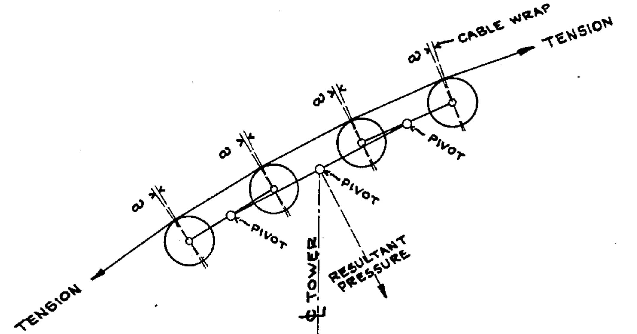
Figure I shows a typical sheave battery having independent pivot points for each pair of sheaves to insure uniform distribution of pressure and wrap. The maximum cable pressure allowed on a sheave varies with the cable diameter, sheave diameter and sheave lining material used. Thus, to allow for proper cable load and wrap, we often have support batteries containing a great number of sheaves. However, the minimum load on a sheave is equally important, and should not be less than 100 lbs for top-riding cable, and 180 lbs for bottom-riding cable.
Further recommended practice is to limit the no-load cable wrap to a maximum of 4½ degrees, and a minimum of 1 degree, per sheave. Unlined sheaves, where still in use, should have lower values for load, and should have a maximum wrap limit of 2½ degrees, since they are more severe on the cable.1
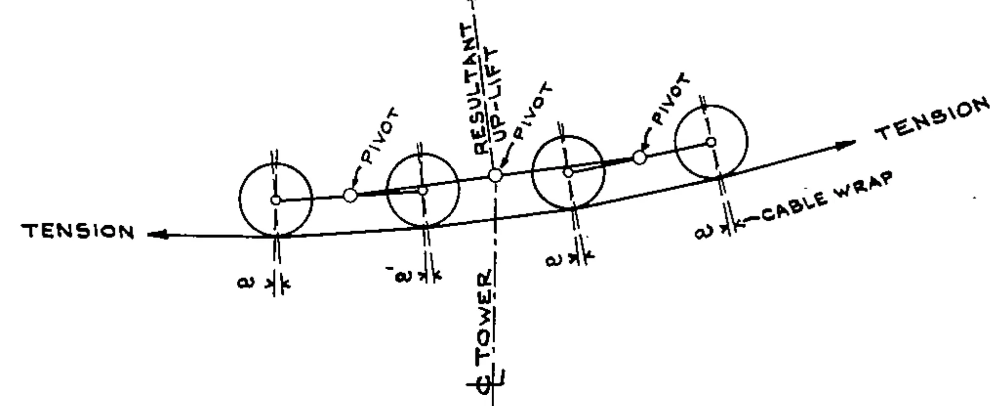
Figure II illustrates a sheave battery with bottom-riding cable. The arrow indicates the resultant direction of uplift on the tower, as produced by the freely articulated sheave units in the battery.
If the graphic diagram shows that the cable, under a particular combination of loads, leaves a support battery entirely, the less experienced designer may be tempted to correct the condition by adding “hold-down” sheaves to the battery. However, this must never be allowed, as it is the most dangerous invitation to trouble imaginable.2

The designer must be particularly alert for signs of cable lift-offs at spans over concave terrain where no hold-down towers are employed. He must also watch for loss of cable contact at sheave batteries with bottom-riding cable. The Europeans, who are working for universal adoption of the “International Safety Code,” are most emphatic on this point.
SANDBAG TEST MISLEADING
The frequently employed sandbag load test may uncover a dangerous condition at a hold-down sheave battery, but it will be of little help at other points. In fact, on the contrary, it may even mislead and give a false sense of security, since it produces practically ideal load conditions by increasing the cable sag and wrap on supporting sheaves. It is of little value as a cable tension test since cable is already amply protected by a high safety factor.
For longer spans and relatively large cable sags it is also necessary to consider aerodynamic factors. The wind may set up cable undulations of sufficient severity to cause derailment or collision with passing chairs or cabins. The horizontal whipping of the cable will also result in impact stresses on the towers, causing unwanted lateral or torsional deflections.
Another annoying and potentially dangerous condition is the vertical cable whip, caused by sudden starting or stopping of the lift. Although both the manual and automatic brakes should have sufficient individual capacity to obtain a deceleration of 100 feet-per-minute-per-second, it may sometimes become necessary to adjust this rate to a value as low as 40 foot-per-minute-per-second before smooth braking is obtained. (If the two units of time used above confuse the reader, one expresses the change in velocity, and the other, the time in which the change takes place.)
There are many other factors which contribute to lift safety than the few we have mentioned. But the factors we have discussed are important since they involve some conditions where the existing safety codes permit liberal interpretation, or do not cover the situation at all. The codes will always require revisions and additional work by the devoted few who were responsible for their adoption, and who have given much of their time in the interest of public safety and public confidence in this relatively young industry.
1 This conforms to OITAF standards; ASA Code does not cover this point.
2 The author’s position contrasts with ASA Code (Para. 3.6.4)