

The trouble with this is that we often dip pretty deep into the safety factor, and every now and then someone “loses it.” This is not only dangerous to our best workmen, but can be damn costly — especially when detensioning of lifts is concerned.
There is the old standard way of picking a fairly flat spot someplace on the profile, kicking the rope off a few towers, dogging the rope off to a tower base and pulling straight away with a heavy piece of equipment. If you are simply rigging for a re-splice to shorten, and if the profile is suitable and the ground dry, this is probably the most expedient way to go. However, I maintain that pulling “straight off” with a Cat is a pretty rough and unrefined way to deal with a ski lift.
There is a better way to handle a rigging job under summer or winter conditions without churning up the slopes, while also eliminating the chance of making a “length” error when splicing. To do this you need a few things:
- Two triple-sheave wire rope blocks for ⅝” rope with a 12-ton rated capacity. Select them with care. My own weight is about 85 lbs. each and one man can carry them.
- Two single-sheave snatch blocks with 8” sheaves; about 6-ton rating.
- One pendant or “tail” of the same rope diameter as your haul rope. (A size smaller is generally O.K.) This should have a thimbled eye in one end and be about 80 feet long.
- One pendant or “tail” as above, long enough to reach from the first depression or portal tower, back and around the bull wheel and back up to a point where its end will be both clear of the depression tower sheave battery and also have enough room to travel without running into anything.
- Three sets of seven of the proper size wire rope clips (“fist” grips are better because they don’t chew your rigging gear up) to fit your haulage rope. Any other proven clamping device, such as the Sauerman Continuous Clamp, may take the place of the fist grip or the U-bolt clips.
- Three or four 1⅜” or 1½” screw pin anchor shackles.
- About six ¾” screw pin anchor shackles.
- Three or four ⅝” x 16-ft. loop — loop slings.
- Two good 3,000 lb. hand-operated cable hoists (come-a-longs).
- Six 2-ft. handy chains or “bitch” chains.
- A 4-wheel drive, one-ton vehicle with a little extra weight will provide sufficient power to lift the counterweight. It has been done many times with a Thiokol Sprite or equivalent.
- One R. W. Diener Sky Jack or equivalent to lift the cable off on one side of Towers Nos. 1, 2 and sometimes 3 and back on again when the job is complete.
Sometimes it’s better in the case of No. 4 to use two shorter pendants, one connected dead to each side of the carriage or to a bull wheel spoke, and reaching out (up the hill) to the same places described in No. 4.
(Incidentally, tramway designers and manufacturers could do us all a big favor by providing a rigging purchase on both sides of the tension carriage just above, and a couple of inches to the inside of, the normal cable path. The same would be a big help at both the upper and lower terminals when it comes time to change a counterweight rope or replace a bull wheel bearing.)
The object of this is to rig in such a way as to allow the haul cable to be removed from the bull wheel. Once this is accomplished it is a simple matter to splice to a pre-determined length that will land the tension carriage exactly where you want it to be. In the process you will have plenty of slack rope for the splicer to splice to your length mark without having to compromise or guess at anything. Some terminal structures will permit the lifting of the cable “up and over” or “out and under” the terminal structure and removing to splicing ground of your choosing. I have spliced crossways to the lift and have made one half of the splice on the uphill side, the other half on the downhill side. I didn’t like doing it this way, but that darned mountain was in the way.
Referring to the drawings, you will notice that Method A is the same kind of a rigging show that would be used if the lift were being rigged some place up on the mountain, assuming you are using tackle blocks and a reeved line. The only difference is that one of the pendants is laid beside the haulage rope through a 180-deg. turn around the bull wheel. You will need the same set of rigging gear and will connect up in the same way. There are, however, two advantages at the base. First, you are working at the lower terminal where access is good; and second, you don’t have to fight for slack — you can get all the slack you need when the rope falls out of the bull wheel.
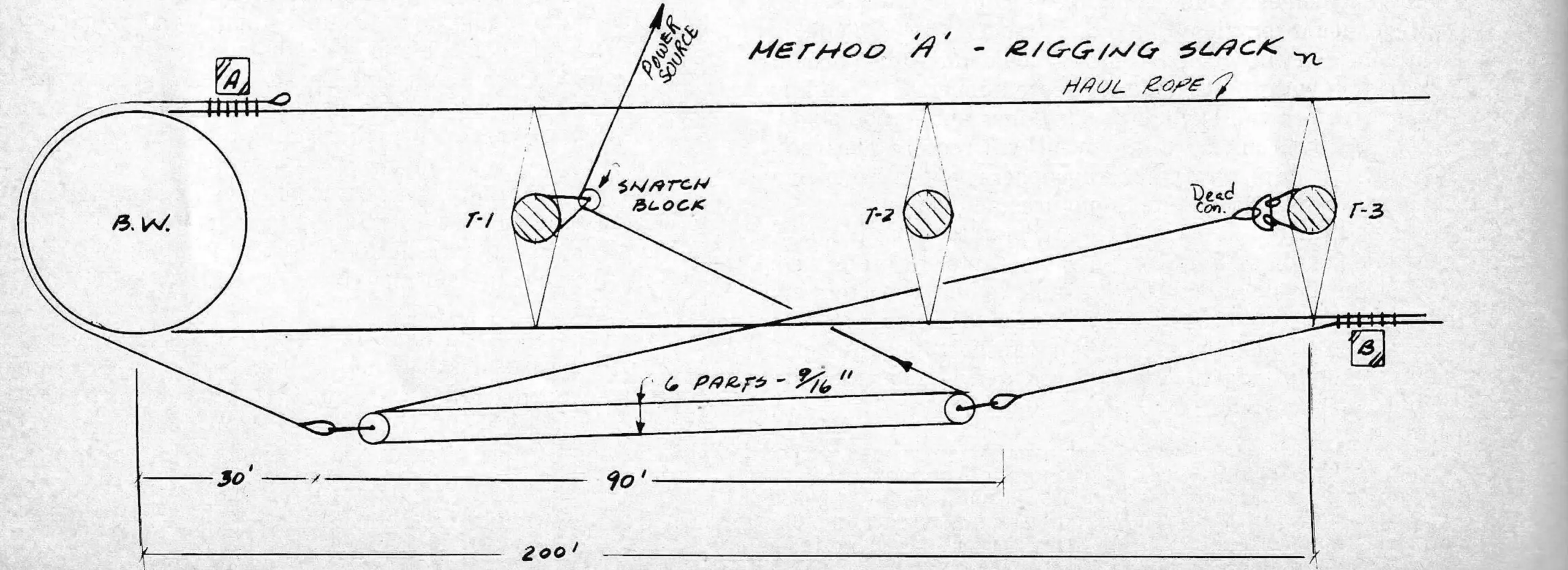
Method B shows the rigging tight, the counterweight is raised and the carriage drawn all the way forward. This illustration is intended to show a new rope being rigged for splicing. The two free ends which are to be spliced are laying free on the ground. The entire rope above the connections ‘B’ and ‘A’ is in place and under normal operating tension.
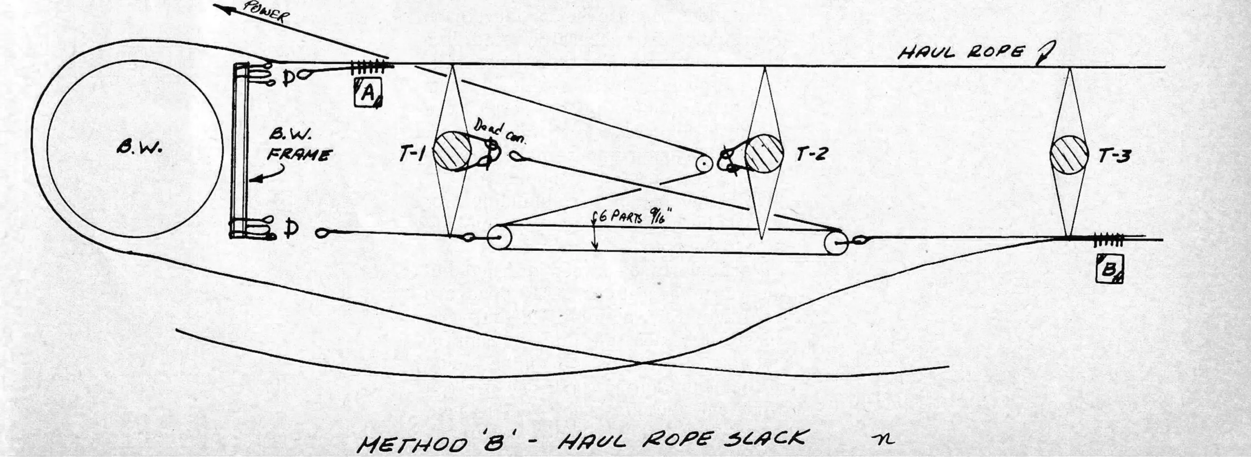
The next operation will be to catch up the free ends by spanning across one to the other with “hand rigging” such as a two-ton come-a-long and a pair of bitch chains or Klein grips. Place the cable in the bull wheel groove, raise it onto Tower No. 2 (the cable catcher is close enough) and tighten until it comes up into the depression Tower No. 1 sheaves. Tighten as much as you can.
O.K., now back off and have a look. Is there any way you can be wrong on your length? The answer is “No,” but you still have to consider the early stretch that is sure to come, so let it rest for a few days. Dog off the reeving line at the snatch block so your pulling vehicle is not tied up, carefully mark the location of the carriage and observe the day-by-day rate of stretch. When it slows down and remains stationary 4 to 7 days you might as well make the length match marks across the two ends where the come-a-long is, pay out on the come-a-long and drop the cable out of the bull wheel groove.
Laying the ends side-by-side on the ground, pull the match marks together and then make an adjustment to compensate for the stretch gained and/or to compensate for the difference from where the tension carriage is now and where you want it to be when the splicing is completed. You are now ready to lay out the splice and all hands can “heave to” to help the splicer do his work.

When the splicing is done, you will have to bring the pulling vehicle back and pull enough more to make up for that adjustment you made by the length match marks. You can then, with the use of two come-a-longs attached to the carriage or — or in the case of Method A, to the pendant — draw enough rope toward the bull wheel to maneuver it into place in the bull wheel groove.
And that’s it. You can clean the rigging off, get drunk or go home. Be sure to give the splicer a good send-off, and don’t forget to pay him. He’s had a rough day.
3 Safety Points
- If you use clips, U-bolts or fist grips, use only the drop-forged steel type. If you have any of those malleable clips take them out and bury them. They are killers! Before starting to make a connection, check the threads, making sure everything will “go” without fighting it, and smear a little grease on all the threads. Then, when the rigging show is all put together, take up the slack and again check everything before making the final pull.
- Avoid clipping a slack rope to a rope under tension. Arrange to apply strain to both cables or to both sides of the eye. This will eliminate the “humps” between the clips and cause each clip to assume its share of the load.
- Be sure to use an anti-twist bar or “lazy bar” or “monkey’s tail,” together with a tag line, on each rigging block and at each haul rope connection. These will stop the “parts” of the reeved line from winding up and will stop the haul cable from rolling out of the sheaves should it be inclined to do so.
In case you want to ask:
Q: Why is the end of the 9 16” reeved pulling line attached to a tower instead of the becket of the block? A. The strain applied by the power source will have the effect of towing the lift cable toward it. The dead end on the tower effectively cancels this tendency.
Q: What about the braking systems in the drive terminal? A: All brakes and anti-rollback devices must be disengaged. The entire cable must be free to self-equalize. There are occasions when it becomes necessary, because of limited travel, to stop one rigging block and cause the other to move while making the pull.
Q: What is the ratio of mechanical advantage? A: If the counterweight weighs 36,000 lbs. the ratio is 36,000 divided by 2 divided by 6 or 3,000 lbs. at the power source, or a counterweight-to-drawbar ratio of 12:1.
Q: With all this rigging gear and cable, how do you keep the lines from becoming fouled or interlaced? A: When planning the rigging show, keep all of the rigging gear toward the “inside” or toward the towers. The lift haulage line and splice are kept to the outside. This way it will raise up and into place free and clear, with no unwanted crossovers, as tension is released into the completed splice.
Q: How important are the anti-twist bars? A: They are essential. Don’t neglect to include them. Use tag lines so they can be held while pulling, and secured while splicing. Two-by-fours will work, but 1” water pipe, with a stopper ring welded 18” from the end, is better. Use this ring or eye with a short length of light rope (rigging string) to keep it from slipping out. A second ring welded at the other extreme end provides a good place to attach the tag line.
One additional comment: On rare occasions it has been possible to drive the lift under its own power, or tow it for a limited distance to make adjustments in the location of the haul rope connections or the rigging blocks. This can be done while rigged in this manner.