


Oddly, there is no ANSI code for roller chain used on ski lifts or people-carriers of any type. I discovered this surprising piece of information when, as a member of the American National Standards Institute’s B77 Committee, I wanted to refer to existing codes in order to revise a section of the Standard.
Upon investigation, I discovered that the elevator industry does not allow the use of roller chains to transmit power for people-carrying elevators because roller chains can fail from fatigue with little warning. Dumb waiters that carry freight, however, can and do use roller chain. Aerial ski lifts, primarily those manufactured by Lift Engineering, also use roller chain.
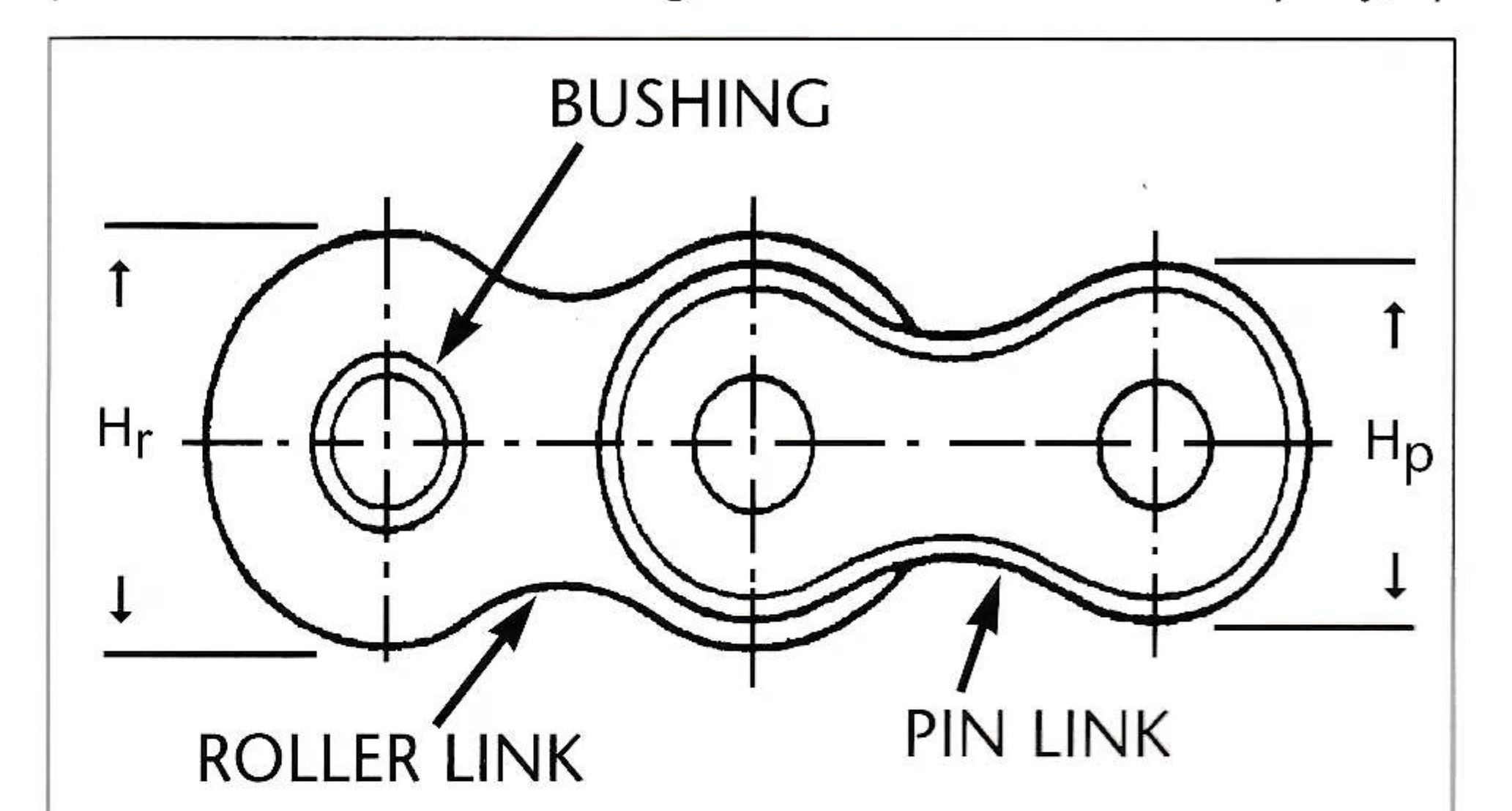
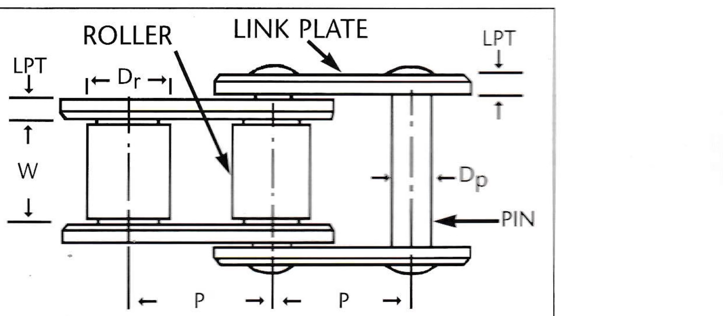
In fact, from the late 1970s to the mid-1980s, roller chain was used on about 110 Yan lifts throughout the world. The chain used on these lifts was #240 with a pitch (pin-to-pin length) of three inches and a weight of approximately 16 pounds per foot with an average ultimate strength of 130,500 pounds.
Although I had this much information, I lacked solid facts to develop a code so I went to the six roller chain manufacturers in the United States. When I told them how the ski industry was applying their product, most of the company executives were very uncooperative. Undoubtedly, because of the liability exposure associated with transporting people, chain company employees would not provide me with needed information. At one major manufacturer of chain, however, I obtained the name of a retired chief engineer. Robert Burk, now an engineering consultant based in Holyoke, Mass., has children who ski and he thought investigating roller chain used on ski lifts would be an interesting undertaking.
The B77 Committee relies on volunteers and does not have a budget, so funding was needed for this project. Chuck Lewis, president of Arlberg Insurance Company, quickly agreed to fund the research in hopes that potential accidents could be avoided.
Field Observations
The next step was to get Bob Burk involved so he could understand exactly how roller chain is used on ski lifts. In August of 1995, he met with a group of ski industry people at Mount Snow, Vt., to review field applications of roller chain. A close inspection of some Mount Snow chain revealed the following:
Chain Length — 10-foot chain sections are connected together to create approximately 100 feet of chain per lift with detachable type Z cotters.
Lubrication — The chain had not been lubricated pending our inspection and appeared dry and in need of lubrication.
Paint — The painted chain was peeling, but in any case, more frequent lubrication is far better than painting the chain.
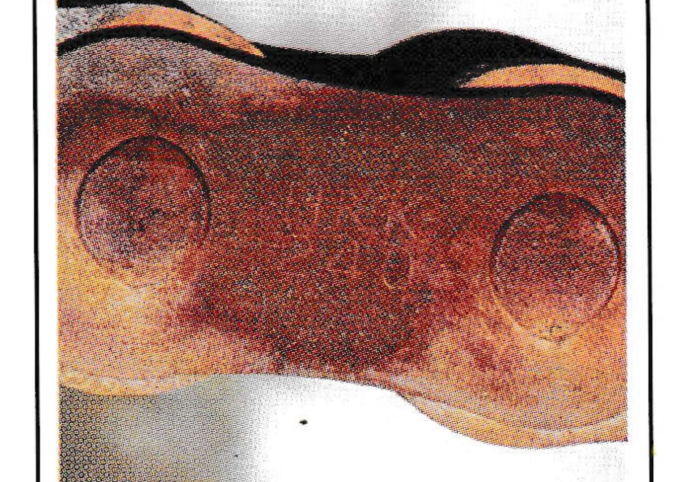
Environmental Effects — Oxidation (rusting) was evident on many of the chain side plates where paint had peeled. Obviously, it was not possible to determine the extent of the oxidation and fretting in the bearing joints without disassembly. A main concern should be eventual stress corrosion cracking at side plate apertures due to corrosion by acid rain and other weather-related factors.
Alignment — There was some misalignment in the horizontal run of the chain system. Both the upper and lower portions of the horizontal system had evidence of side bow, which resulted in rubbing and abrasion on the inside of the link by the sprocket during chain engagement. Misalignment is not a serious condition in view of the relatively slow movement of the carriage.
Sprocket Size — The 12-tooth sprocket at the carriage location was under the 15-tooth minimum recommendation for power transmission systems. In view of the extremely low speed of this particular application, however, the chordial action did not result in rough operation as it would have in a high-speed application. (Chordial action is the rise and fall of the chain links as they engage and disengage the sprocket teeth.) Therefore, a 12-tooth sprocket is acceptable.
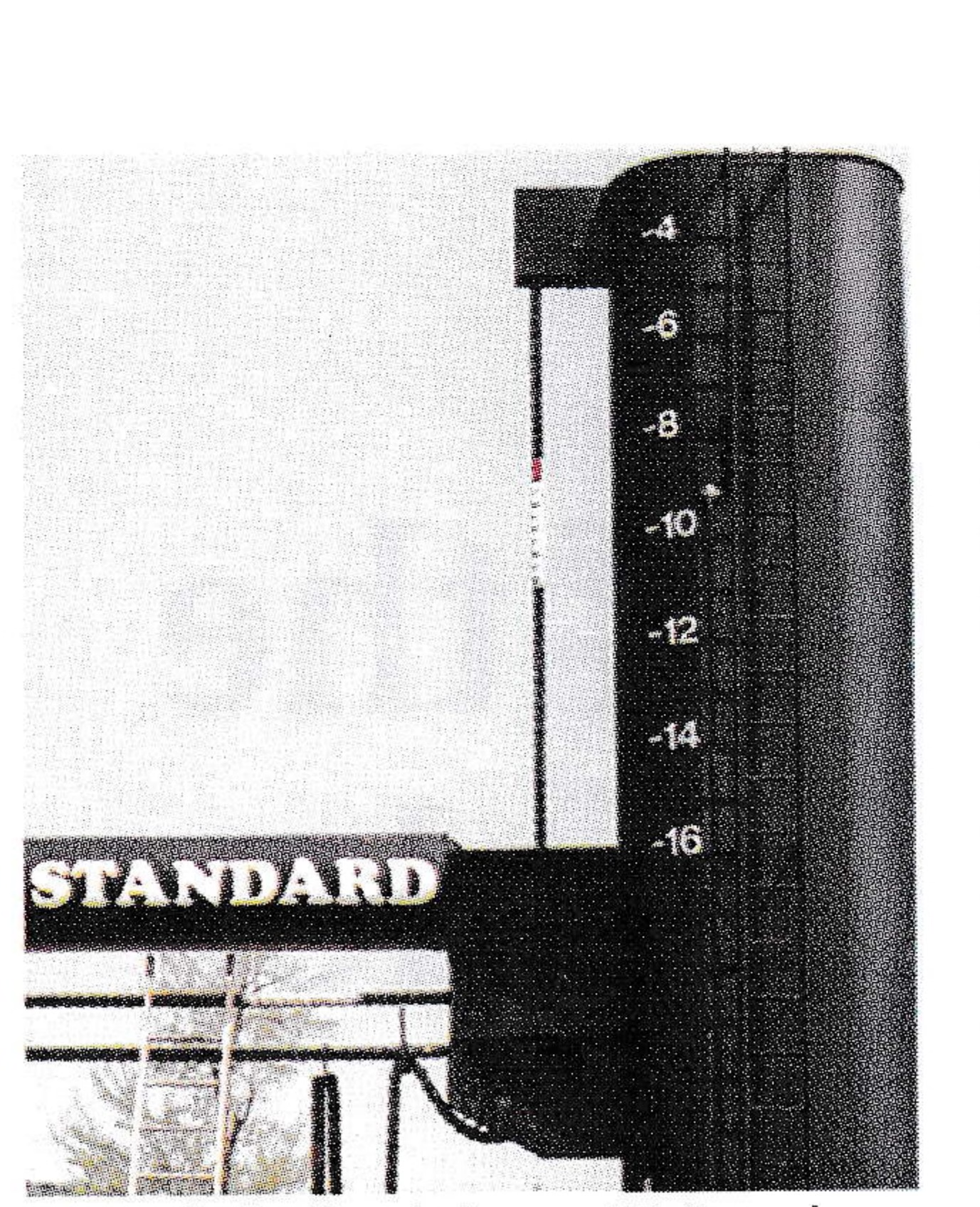
Chain Elongation — A painted section of chain in a vertical strand indicates where the chain is measured periodically to detect elongation. Burk advised that the chain be measured for elongation at a location where the chain had been and would continue to be engaging and disengaging a sprocket. This is the area where chain wear takes place due to articulation of the bearing joints. In the vertical strand location, there is no sprocket engagement, therefore no elongation would occur from wear.
Chain Slack Strand — If at all possible, the chain should be out of tension when it is lubricated.
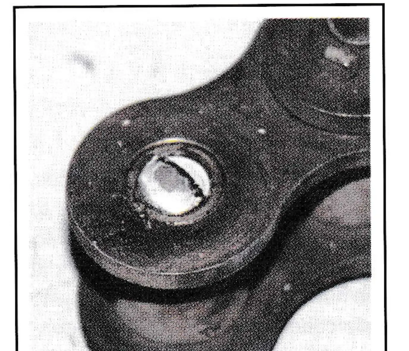
Clevis End Connection — These connections consisted of “pin connections.” But, it could not be ascertained whether the pins were case or thru hardened, or what type of steel, carbon or alloy they were made of. It was suggested that this information be obtained because it is important that the clevis pins be of higher strength or at least equal strength to the chain pins. (Park City, Ut., subsequently tested pin hardness and found it to be Brinell 220.)
Chain Work Load — A load of 18,000 pounds is imposed on the chain strand from the counterweight. The minimum ultimate strength (MUS) of a #240 chain is (using the American Chain Association method of calculation) as follows:
MUS = 12,500 lbs. x (pitch squared) = 12,500 x 9 = 112,500 lbs.
M.U.S. / Work load = 112,500 / 18,000 lbs. = 6.25
Shock Loads — The probability of shock loading does not appear to be a major concern, but it could result if trees fell across the cable.
Temperature — A chain subjected to low temperatures of -40F is considered cryogenic. This is a condition where brittle transformation begins to take place in steel, but alloy steel is affected less than regular carbon steel. Generally, standard #240 chain materials consist of 5140 alloy, medium carbon for side plates, 4320 carburized alloy, low carbon for pins and equivalent for carburized bushings. Rolls are usually thru-hard alloy material, medium carbon. Therefore, cryogenic concerns for chairlift applications are slight.
Maintenance — Procedures provided by the lift system manufacturer for reference as a routine inspection and maintenance procedure were reviewed.
Field Inspection Conclusions
After observing and discussing the details of roller chain application on ski lifts, a course of action was agreed upon to justify final decisions made as to the adequacy of a chain assembly in lift systems.
Maintenance Manual — Regardless of the final outcome of this investigation, a more comprehensive maintenance procedure and manual for roller chain should be developed.
Testing — Chain sections from various lifts (five or six from different areas of the U.S.) would be sent to an independent lab for the following tests and analysis:

- Tensile tests to determine the level of chain strength remaining after years of service, exposure to elements and bearing wear, and then comparison to the original rated average ultimate strength.
- Examine the type of failure resulting in a tensile test—normal or abnormal—and causes if they are abnormal.
- Examine internal bearing surfaces of component pins and bushings for the extent of wear, galling, fretting, pitting, etc.
Sam Geise, of Acordia Resort Services, and I put together a maintenance and inspection document for roller chain based on technical information from Bob Burk. The document serves as an educational piece as well as a maintenance manual and has been distributed to authorities having jurisdiction, chain users and ski industry engineers.
Rich and Jim Boyko of Mill Valley Splicing in Belchertown, Mass., agreed to do the tensile testing and several ski areas across the country were contacted for samples. Park City, and Eldora, Colo., had chain in storage that had been replaced, so that was easy. Deer Valley, Ut., and Killington and Mount Snow, Vt., agreed to get samples from in-use chain, which proved to be a huge rigging challenge as the counterweight is fully enclosed with no access under the weight. To further complicate matters, the pins are pressed into the side plates of the chain with an interference fit of .005 to .008 inches, so the pins would have to be pressed out.
After several months the chain samples were obtained and shipped to Mill Valley for the tensile test and inspection in January, 1996.
| Specimen Number | 1 | 2 | 3 | 4 | 5 |
|---|---|---|---|---|---|
| Chain Origin | Steamboat | Deer Valley | Park City | Killington | Mt. Snow |
| Manufacturer | D.I.D. – Japan | D.I.D. – Japan | Link Belt – U.S.A | S.Y. – Japan | S.Y. – Japan |
| Construction Type (Detachable) | Double Cotter | Double Cotter | T-Cotter | Z-Cotter | Z-Cotter |
| Years Service | 8.5 | 14 | 11 | 11 | 13 |
| Average Ultimate Strength (lbs.) | 130,000 | 130,000 | 130,000 | 130,000 | 130,000 |
| Minimum Ultimate Strength (lbs.) | 112,500 | 112,500 | 112,500 | 112,500 | 112,500 |
| Actual Ultimate — (Failure lbs.) | 135,460 | 138,310 | 112,530 | 139,540 | 141,500 |
| Resultant Type Failure | P.K.S.(1) Clevin Pin | P.K.S.(1) Chain Pin | P.K.S.(1) Chain Pin | P.P.S.(2) Pin Plate | P.P.S.(2) Pin Plate |
| Corrosion (Rust, fretting, red oxide) | Yes – Mod. | Yes – Mod. | No | No | No |
| Pitting | Yes – Sl. | Yes – Sl. | No | No | No |
| Galling | None | None | None | None | None |
| Lubrication | Poor To Void Of | Poor To Void Of | Fair | Good | Good |
| Wear — Pin Bearing Surface | Very Slight | Very Slight | Very Slight | Very Slight | Very Slight |
| Contaminants (Dirt, grit) | Slight | Slight | None | None | None |
| Pin Diameter — Measured | .036″ | .935″ | .932″ | .938″ | .935″ |
(1) P.K.S. = Pin Knuckle Shear (normal and expected). Indicates pin toughness and ductility. (2) P.P.S. = Pin Plate Shear—Acceptable (if above minimum ultimate strength). All specimens consisted of 4 roller links and 3 pin links except #1 due to insufficient links shipped for test.
Test Results
Test results indicated no severe or significant reduction in tensile strength due to any conditions of operation or exposure to the environment. The chains, if representative of the samples tested, are in good condition after maximum life experience of 14 years on a sample.
If roller chains are properly maintained and lubricated regularly, a reasonable supposition could be that at least an additional five years of service life can be expected beyond the 14 years experienced to date. The area of greatest concern should be that of pitting, which can lead to and serve as a nucleus for sudden failure.
Overall, tests revealed the following:
Seizure — Prior to destructive testing, Burk flexed chain joints and rotated rollers in each specimen. No stiffness of joints or seized rollers was evident.
Strength — All five specimens “pulled” above minimum ultimate strength and four specimens exceeded average ultimate rated strength.
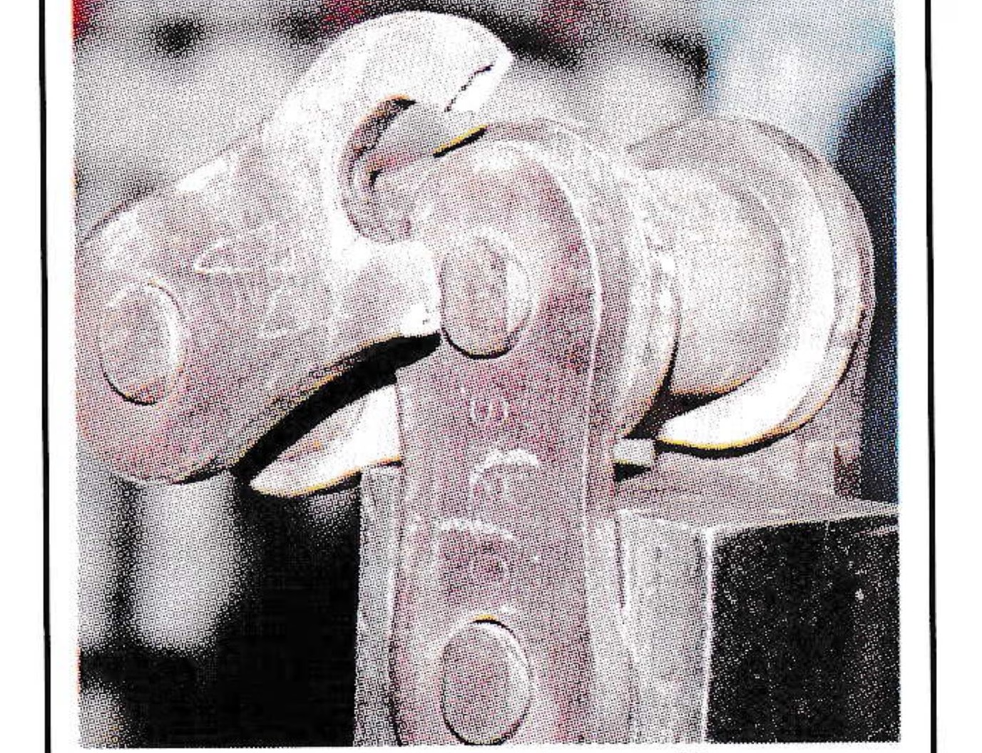
Fracture Type — Specimens 1, 2 and 3 (western area chains), demonstrated normal and acceptable fractures with “Pin Knuckle Shear” that typically indicates strength, toughness and ductility, all important characteristics in chain pins. No straight pin shears occurred, which would indicate brittle behavior. Specimens 4 and 5 (eastern area chains), demonstrated abnormal but acceptable fractures with “Pin Plate Shears” rather than pin failure. This is acceptable, because the failure point is seven to nine percent higher than the average ultimate strength and also higher than the normal pin fracture in specimens 1, 2 and 3. (A possible reason for lack of pin fracture in specimens 4 and 5 could be use of thru-hard rather than case-hard pins.)
Embrittlement — There were no indications of low temperature embrittlement due to grain structure transformation at cryogenic temperatures. All pin fractures exhibited ductility. The pin plates on specimens 4 and 5 also exhibited ductility by elongating prior to final separation.
Contaminants — Although all specimens had some degree of dirt and rust on their exterior surfaces, all of the bearing joints were relatively free of foreign matter such as dirt and grit. There was, however, internal rust in specimens 1 and 2.
Bearing Corrosion — Specimens 1 and 2 exhibited moderate corrosion and slight pitting on the inner bearing (pin) surfaces. Lubrication appeared to be only residual from the original factory lube as it was tar-like in substance and almost non-existent. Specimens 3, 4 and 5 were void of any corrosion on bearing surfaces (specimen 3 operated indoors). Specimens 4 and 5 were well lubricated, which accounted for the absence of corrosion. It was revealed that 4 and 5 were lubricated on a regular basis.
Bearing Wear — Wear was insignificant with no measurable reduction in pin diameter, but bearing areas exhibited a slightly rubbed appearance. Lack of wear was expected due to the very slow speed and minimal articulation inherent in the application.
Recommendations
When comparing specimens 4 and 5 to other specimens, a lack of bearing corrosion and good lube condition indicates heavy emphasis should be placed on lubrication efforts in all applications. This includes detensioning of the roller chain every year.
Considering the lack of established replacement criteria by designers or manufacturers, periodic monitoring of tensile strength, bearing component condition and other internal components should be performed every five years or even more frequently. Results should be compared with inspection results from previous years, and then appraised for possible action.
Future testing of other manufacturers’ chains that have been used in the ski industry, but were not included in these tests, is recommended. (Mill Valley is set up for this testing and Bob Burk lives nearby.)
Pending further testing, it is recommended that roller chain be replaced after 20 years of service. This is considered a conservative approach with the lack of proper maintenance procedures and records, and allows ample time to plan for replacement.