


This familiar “sonic” echo has been conducted by most of us at one time or other. Being basically intelligent folks, we realize the echo that returns from the “source” (our voice box) is simply rebounding sound which has been reflected off canyon walls, transmitted back through the air and received by our ears. This is sonics — the utilization of reflected sound waves for particular reasons.
Sonics Principles
The speed at which sound travels is directly related to the medium or material through which it passes. When air is the material, as above, sound cruises right along at 1,100 fps or 750 mph (sea level). However, if water is used as the medium the velocity jumps up to nearly five times that in air; and if steel is the medium, 14 times.
Returning to our echo for a moment, let’s suppose two people hear the reflected sound (echo) and each tries to describe it. Certainly, the descriptions will differ, maybe slightly, maybe substantially. Therefore, wouldn’t it be better to analyze this echo electronically, and, for even greater control, substitute an electronic sound source for the operatic Helloooo?
The electronic source for testing is a million cycles per second (cps) — well beyond the 20 to 20,000 cps range of the human ear. In order to detect small interferences in the sound path, small sound waves are necessary, and these are generated by higher frequencies. For example: the small, closely-spaced ripples generated by dropping a pebble into a pond can easily be interfered with by placing your hand in front of a wave. Conversely, if you pull that trick on the California coastline, the large, well-spaced waves there wouldn’t even know you had raised your hand.
Ultrasonics
Now that we are into the nonhearing range of one million cycles per second (one million Hertzians, or 1MHz), we cannot detect changes in frequency by ear. Therefore, the information is transformed electronically into a controllable source and readable echo.
The sound source, or vibrating part, is a crystal with a special property called “piezoelectrics.” This allows the crystal to be directly vibrated with an alternating or oscillating current at very precise frequencies. In addition, the ultrasonic waves they generate are not only strong but are concentrated in a very narrow beam. On a large scale, the crystal or “transducer” can send a narrow beam from a ship to the depths of the ocean floor or to a school of fish. The time it takes for the sound (echo) to be reflected back to the ship is a direct measure of the depth of the ocean, or the fish.
On a small scale, the waves can be made to pass through solid substances such as aluminum castings, bullwheel shafts, and even fat on lean meat. If there are breaks in the solid, or a change in the density, stray echos will usually show up on an oscilloscope to give an “ultrasonic picture” of the inside of the material.
Development
Though the “piezoelectric” qualities of certain crystals were established in 1880, it was not until the 1930’s that they were harnessed to ultrasonic sound waves for testing purposes. At that time, inspection methods were developed that required access to both ends of the test specimen and were limited to locating only the larger flaws. Then in 1940 Fred Firestone presented an instrument that employed the “pulse-echo” concept and embodied it in one transducer. Thus, the accurate measurement of reflected sound energy was finally available and has since been expanded into a very reliable and often complex system of nondestructive testing.
Testing and Indications
Now we’ve arrived at the easier portion of this presentation, relatively speaking. Let’s assume you wish to test the continuity or structural soundness of a stub-end bullwheel shaft. And for simplicity’s sake (and mine), the shaft is without shoulders, tapers or keyways; and the length is known.

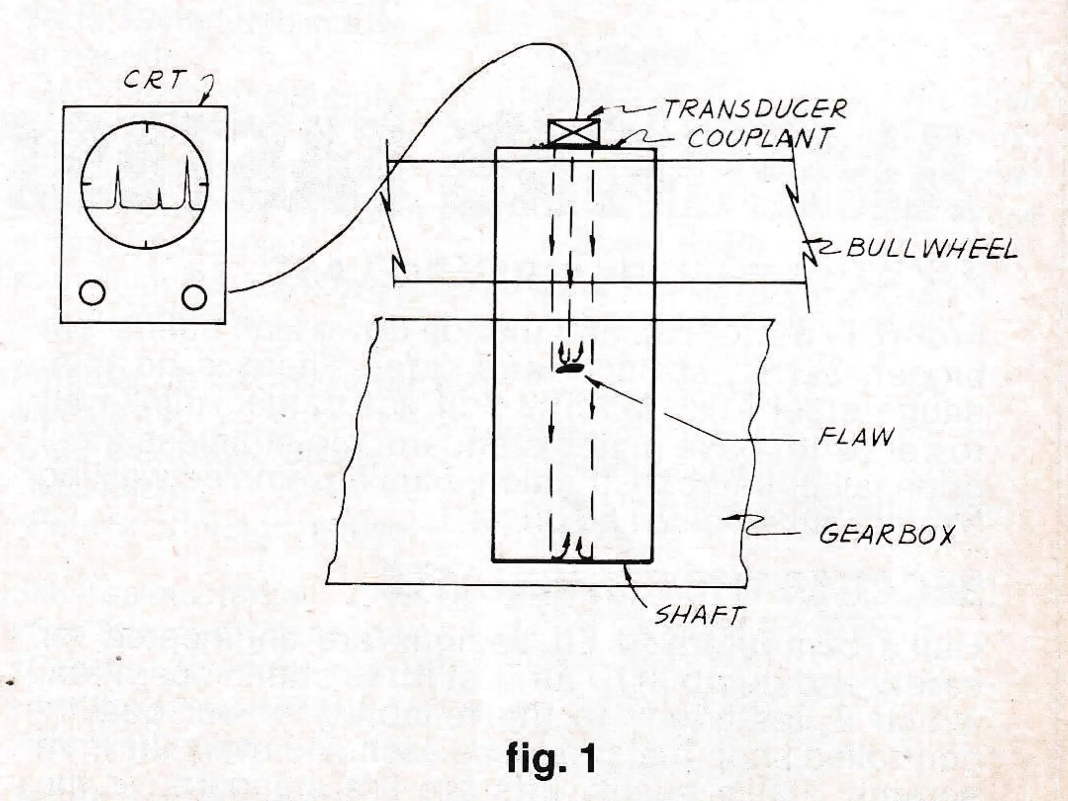
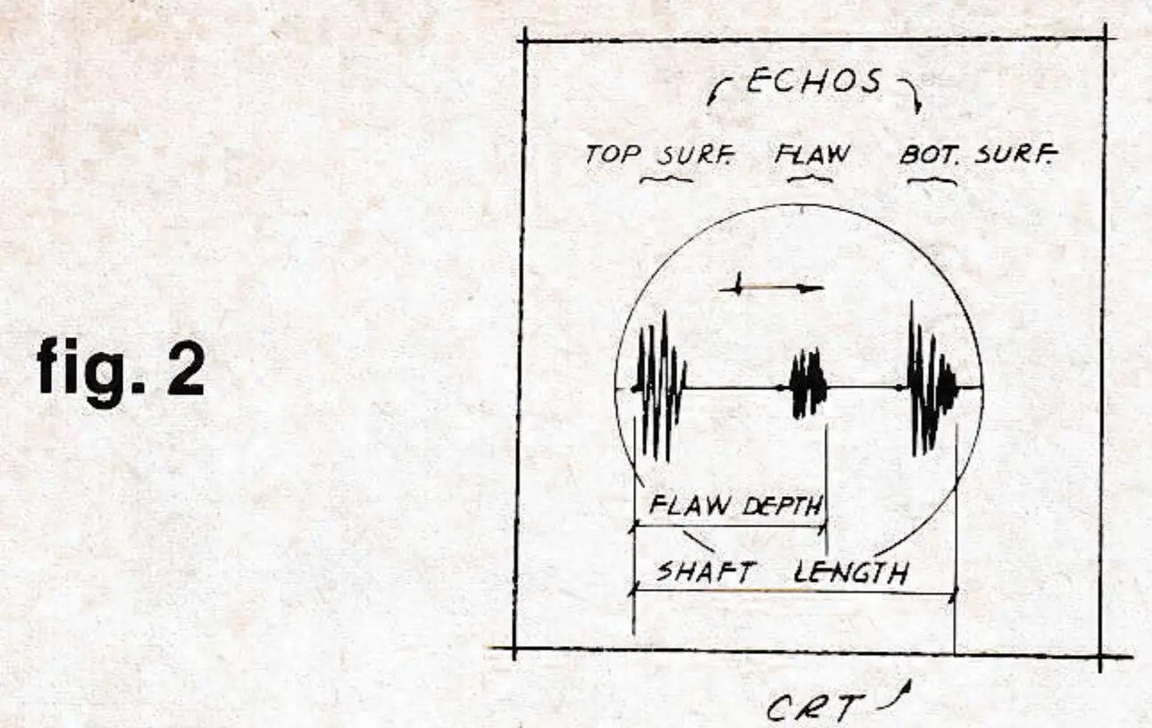
The free end of the shaft is cleaned and polished prior to testing. The transducer (see fig. 1) is attached to a “CRT” (Cathode Ray Tube, or oscilloscope) with a coaxial cable, and the CRT plugged in. Then a “couplant” material, liquid or paste, is spread on the test area and the transducer placed on top. After initial and important adjustments are made to the instruments, testing begins. A series of evenly timed pulses of ultrasonic waves are transmitted into the shaft. The “echos” or reflections from either discontinuities or the shaft bottom and edges return through the transducer and into the brains of the outfit, the CRT. The picture presents (fig. 2) a clear indication of what is inside the shaft to any certified technician, who in turn presents you with a written and verbal report. Please note that the evaluation process is the most important aspect of this test and others and must be accomplished by personnel familiar with the components being tested and equipment being used.
Decision Making
If a flaw (perhaps not a defect) is encountered, you have several choices: (1) Do nothing and send the guy home; (2) Ask for verification with different equipment or technician; (3) Call in another outfit and rerun the test; or (4) Remove the shaft from service and have it lab tested and/or X-rayed. Prior to removing the shaft, you would be well advised to call your supplier, since his experience could save you needless expense.
Industry Applications
Ultrasonics has been employed in the testing of bullwheel shafts, anchor bolts, sheave axles, evener frame axles, rope grips, chair/cabin hangers, and wall thickness on tube-type towers. All of these tests can be, and have been, performed “in place” with varying degrees of success. Herein lies the basic problem with UT in the ski industry: There is a healthy disagreement among experts regarding the reliability of testing in-place. This applies especially to chair grips and clips.
One lab, Buckeye Testing, reports getting good results either way when checking grips, and they’ve done thousands. However, reliable data is a direct function of experience and knowledge of the specimen to be tested. Howard Anderson, a top ski area insurance inspection engineer, agrees wholeheartedly. In addition, he emphasizes the “firm should have samples with known visual defects as a guide, and provide a written report when finished.”
There are several advantages of UT over other nondestructive testing methods. It is not especially temperature sensitive and can more easily accommodate complex shapes. It is fast and provides a direct indication which requires no developing time. Finally, strip chart recorders can make permanent records of data if necessary.
Since costs vary according to component location, weather, and sometimes technical ability, don’t let dollars be your only guide. For planning purposes, you can expect roughly 15 minutes each for sheave axle and grip, and up to four hours for a complete tower check of weldments and metal thickness, depending on accessibility and advance preparation.
Ultrasonic Testing is an extremely accurate nondestructive testing procedure when done by trained and knowledgeable personnel. There is no question that guidelines are needed in this regard, not only from component suppliers, but also from the industry as a whole. Any development of standards should come from within the ski industry for the ultimate benefit of everyone in the industry.