

A number of factors favor combining the traction rope tension and drive systems in the same terminal of an aerial passenger tramway. The factors include the location of power source for the prime mover, simplification of the logistics problems during the erection phase by having most of the machinery in one location (usually at the lower terminal and the advantages accruing to the operational phase of having the primary machinery components concentrated in one easily accessible location.
For most aerial passenger tramways of the chair lift type, it is desirable to have the loading and unloading areas as open and clear of structures as practicable so that the ingress and egress of the passengers will not be obstructed, and in the case of ski lifts, to provide clear space for snow control vehicles to operate.
It is self-evident that to provide clear open space as described it is necessary to locate the tension-drive mechanism above the loading-unloading area, with the supporting structures located preferably to the sides to allow completely free passenger and vehicular travel through the terminal. The basic loads and forces the design engineer must consider are those imposed upon the structure by the traction rope, the torque of the traction rope drive machinery, the dead weight of the terminal structure, wind loads, and the seismic forces applicable to the project locations.
The design of elevated static structures presents no unusual problem, but the problem to be solved is how to provide reaction on a combination tension-drive platform to resist the torque from the traction rope drive. The conventional method is to utilize rigid rails attached to terra firma through a structure, and to have the carriage equipped with rollers to react against these rails so that the torque created by the drive is transferred to the rails. These rails are disposed parallel to the longitudinal axis of the tramway, and must be able to resist the forces imposed upon them by the carriage. Sketch No. 1 shows the typical plan view of a conventional combination tension-drive carriage with the traction rope, T1 and T2, reacting on the drive sheave. The carriage is connected to a counterweight or other tension regulating device by C. The carriage is supported by rails reacting on support wheels at the corners (not shown). During operation when the tramway is loaded, T1 increases and T2 decreases to provide the force to move the traction rope and its load. (The sum of T1 and T2 is always equal to C.)
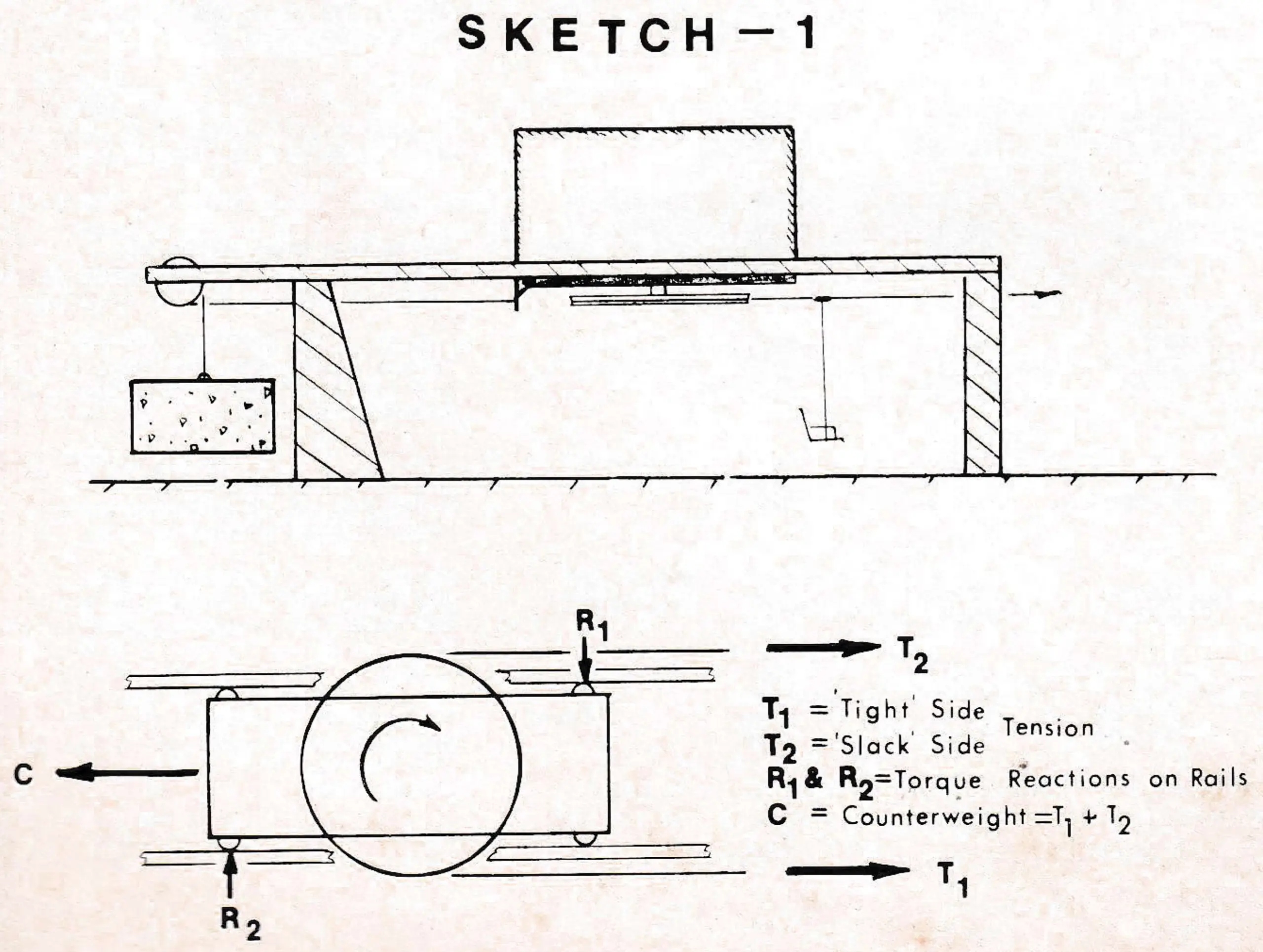
It is evident that the carriage will attempt to rotate in a counterclockwise direction as an equal and opposite reaction to driving the traction rope. To prevent the carriage from rotating, the conventional system employs rollers reacting on the support rails in a horizontal plane. The reactions are shown on Sketch No. 1 as R1 and R2 and in this configuration are equal in magnitude and opposite in direction. Forces applied in this manner are called a couple, and the torque value of the couple is the product of the force R1 times the perpendicular distance between R1 and R2. This torque, of course, is equal to the torque created in the carriage by the traction rope drive, but opposite in direction.
This system functions satisfactorily, but the requirement to design the supporting structure to withstand the reacting forces R1 and R2 on the support rails, while still providing the clear space desired, has caused most design engineers to compromise the desired configuration, and in fact to locate parts of the supporting structure in the area desired as clear space.
The optimum solution eliminates the need for the rails to take a horizontal reaction, since the arrangement provides for all of the forces caused by the drive to be taken through the counterweight ropes.
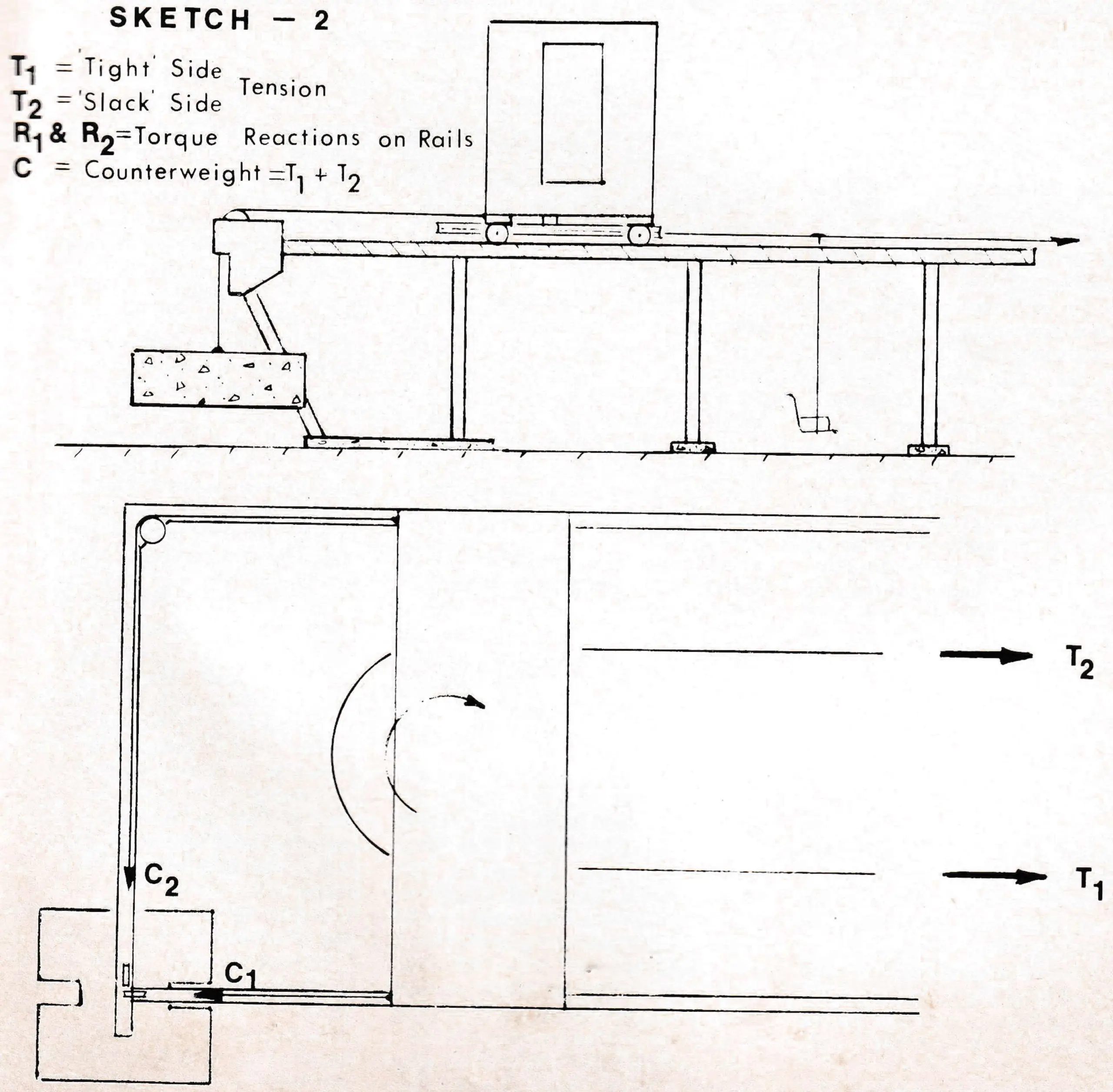
Referring to Sketch No. 2, the overall terminal consists of stationary elevated rails which support a traveling tension-drive platform No. 1. As the loading of the tramway is changed or as the ambient temperature changes or as the traction rope stretches, the drive carriage No. 1 must move back and forth to maintain the same tension relationship in the traction rope, and this is accomplished by attaching the counterweight to the carriage. This is usually attached to the carriage in such a way that the counterweight ropes are disposed in a straight longitudinal line from the attachment to the the tension carriage to the attachment on the counterweight, and thereby the counterweight ropes do not provide a compensating torque upon the tension-drive carriage.

The configuration in the sketch shows the counterweight ropes attached to the tension-drive carriage in a spread fashion so that if the counterweight ropes C1 and C2 vary in tension, they in turn will impose a torque upon the tension-drive carriage No. 1. Note that the counterweight ropes could be spread any distance apart from the centerline and attain this result, and the configuration shown is merely for the illustration of this principle. It is understood that C1 and C2 are rigidly attached to the counterweight; therefore, the tensions C1 plus C2 will always be equal to the counterweight and in accordance with the freedom of movement of the tension-drive carriage T1 plus T2 (the tensions in the traction rope) will also equal the counterweight.
To illustrate the principle involved and the method of solving the problem, we have to assume that the tramway is loaded and T1 is larger than T2, therefore causing the tension-drive platform in the view to attempt to rotate in the counterclockwise direction. This resultant torque will cause C1 to increase and C2 to decrease by the same amount, thus maintaining a state of equilibrium whereby C1 plus C2 equals the counterweight and also equals T1 plus T2 due to the configuration. It can readily be determined that the torque created by the difference in T1 and T2 on the tension-drive carriage is reacted by the change that occurs simultaneously in the counterweight ropes C1 and C2, thus eliminating any couple foces from the tension-drive platform that would have to be reacted by the rail structure.
As mentioned previously, the exact spread of the counterweight ropes in relation to the traction ropes can be varied depending upon the exact forces and configuration desired. It is only necessary that the counterweight ropes be attached in a spread configuration so that the difference between the tensions in the counterweight ropes will apply a torque to the tension drive carriage. It is necessary that the two counterweight ropes be joined to the counterweight at the same point so that the sum of the tensions in the two counterweight ropes will always be equal to the weight of the counterweight.
From this analysis, it is apparent that there are no lateral loads placed upon the carriage rails by the tension-drive carriage. The only loads the rails and supporting structures must withstand are those caused by wind and siesmic forces.
An inspection of the other views of the terminal will disclose that the first tower machinery of the tramway is supported from the overhead cross brace between the rails and that the entire area of the terminal is completely clear of obstruction as per the basic desired criteria. When fixed drive terminals are used, the tension-drive carriage is mounted on supports on each side, leaving the space underneath completely clear.
A U.S. patent has been allowed for the tension-drive configuration and a Canadian patent is pending.