


In the last issue of SAM (Summer 79), we discussed the most basic of all NDT methods, Liquid Penetrant testing. Although comparatively simple compared to the other types of testing, LPT was shown to have numerous limitations. It will not indicate sub-surface “discontinuites” nor will it allow testing in cold temperatures. In addition, the dwell times involved in “penetrant” drying after removal and initial penetration are critical. Finally, LPT may not disclose tight discontinuities which may be potential “defects”.
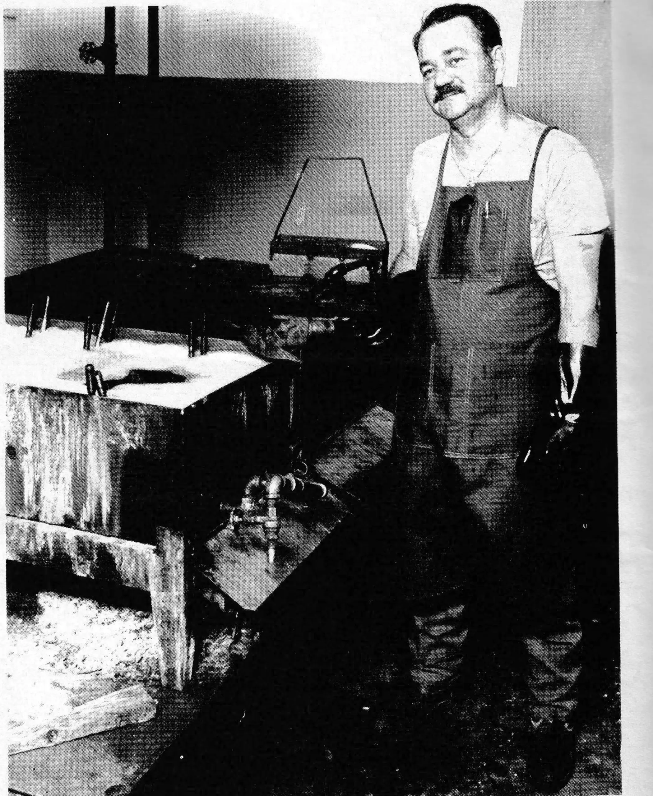
Magnetic Particle Testing (MT) is the second of four non-destructive tests that can be used by the ski industry to control the quality of the many mechanical components which are found at most ski areas. While no individual test will guarantee failure-free operation they will, when properly selected and performed, provide a high degree of assurance that the intended quality is still present.
This assurance is a direct function of the capabilities of the inspector and the accuracy of the equipment in use. Most of us in the industry have long associated the name “Magnaflux” with magnetics testing. As you may have guessed from the article on LPT, Magnaflux is a trade name, just as Dubl-Chek is for liquid penetrant testing. Regardless of the name, MT is widely accepted as “the” way to inspect chair grips and similar component parts. But, just how does it work?
Magnetic Principles
The principles behind MT are as basic as “Lodestone” or the simple horseshoe magnet you played with as a youngster. Remembering that every magnet has at least one set of poles, (fig. 1) north and south and that these poles will attract iron or ferrous type particles, will help form the basis for understanding MPT. These magnetic lines of force (fig. 2) or “flux” are very reliable and exhibit definite characteristics such as: they form closed loops; they will stretch and change shape like rubber bands; they never cross; they seek the path of least resistance; they are most dense at the poles; and they flow from N to S outside the magnet and S to N inside.
For instance, if you were to interrupt the lines of force with a steel bolt, they would assume the path of least resistance and some of the field would pass through the bolt from N to S (fig. 3). This phenomenon is true regardless of whether the magnet is a “permanent” type (the horseshoe) or is “induced” at will with an electic current—an electro-magnet or solenoid.
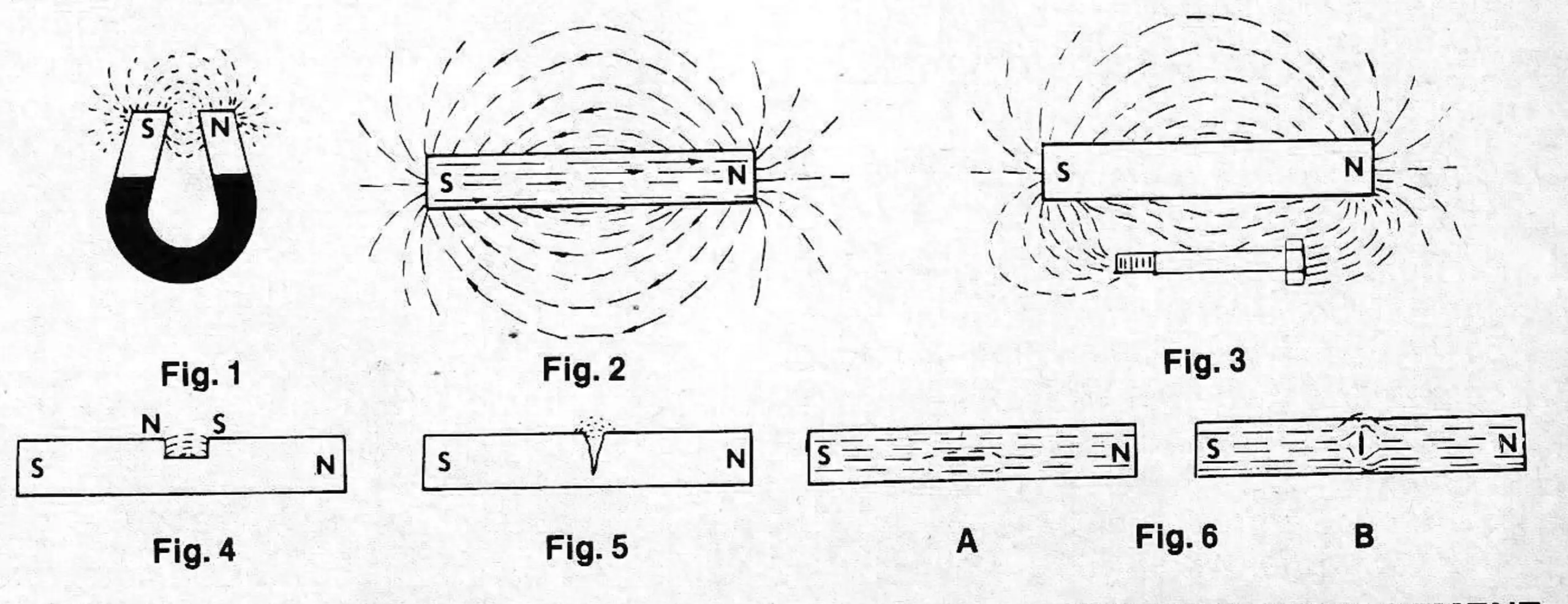
Staying with the permanent magnet for just a moment, what will happen if the bar magnet shown above is broken in two? Very simply, you now have two magnets for the price of one, each with its own set of poles. Now suppose, instead of breaking the bar completely, you file a notch in one edge as in (fig. 4). Two opposite poles (N & S) are formed at the notch and a local “leakage field” is formed. This important characteristic of ferromagnetic materials provides the basis of magnetic particle inspection.
MT Basics
Leakage fields are formed at the poles of any break or “discontinuity” and are the lines of force which leave the material to pass through the air from one pole to another. It is this sudden change of material density or permeatbility that causes the leakage. Now, if we were to sprinkle fine particles of ferromagnetic material in the vicinity of this discontinuity, the particles (like the bolt in fig. 3) offer a path of least resistance and tend to outline the leakage field, since they are held there by the local magnetic field. (fig. 5) So, that’s all there is to MT, right? No, not quite.

Magnetic Particle Indications
The ultimate purpose of magnetic particle inspection is to locate flaws which are defects that render the material unsuitable for use. It is most important to remember that MT does not indicate defects; It discloses leakage fields which may or may not be defects.
The amount of “leakage” caused by a flaw or discontinuity is influenced greatly by its location relative to the direction of the magnetic field and depth from the surface. This principle can best be explained by what happens when you extend your hand out the window of a moving car. If it is held palm facing the direction of travel (karate chop position) a great deal of force is felt and air turbulence is created. But, when held parallel to the flow of wind, there is little resistance and minimal turbulence created. Similarly, a thin crack in a ferromagnetic piece of material that runs parallel to the lines of force will cause little disturbance and produce very little leakage field (fig. 6A). However, when at right angles, a stronger leakage field is produced (fig. 6B). This principle continues to apply in various cases depending on the shape, size, and location of the flaw. When the flaw reaches and breaks the surface of the material, maximum field leakage occurs. Thus, various conclusions can be drawn: cracks which reach the surface are more easily detected than more streamlined types such as porosity and slag holes; the flux or lines of force should be at right angles to the flaw for greatest sensitivity; and to assist in obtaining reliable indications, the flux should be induced in at least two directions, at right angles to each other.
Applications
How does all this cleverness apply to the ski industry in general, or your area in particular? At present there are few codified requirements for this type of continuous testing of lift components, and none for vehicles, pumps or other moving machinery. However, some areas, in addition to the required grip testing, are using NDT selectively throughout their operations. Such items as anchor bolts, bearings, and walking-beam pins can be checked easily with another form of NDT called “ultasonics”. Magnetic testing on the other hand is limited, or of little use, in these areas since the piece to be checked must be somewhat portable and usually must be removed from service for complete testing.
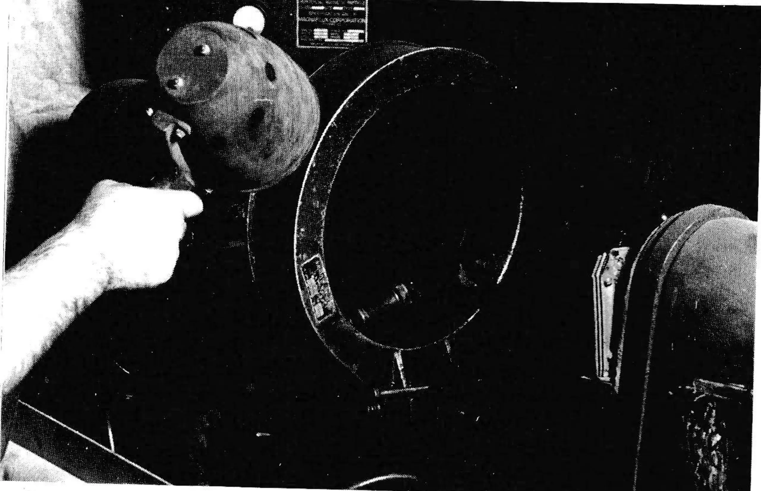
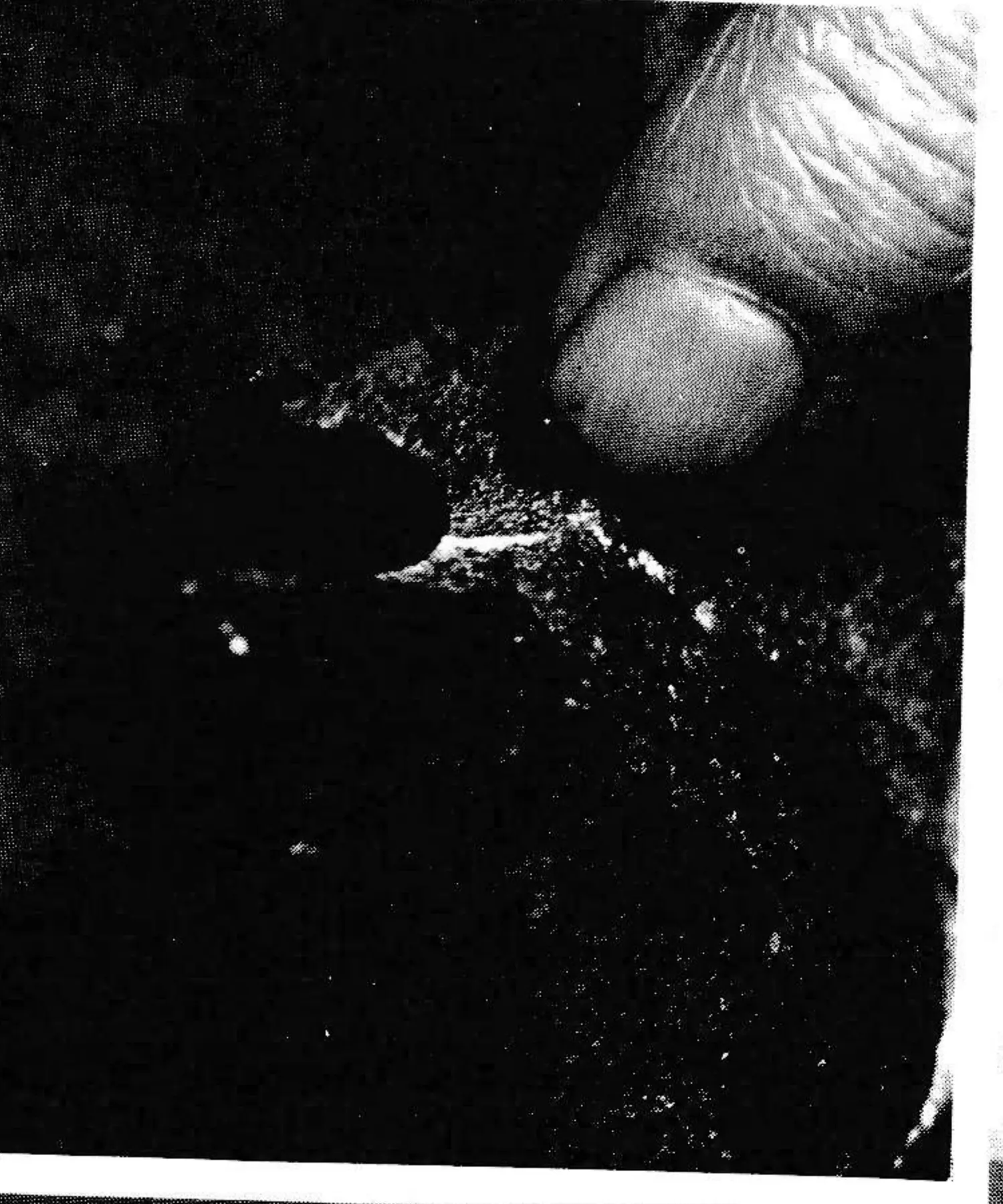
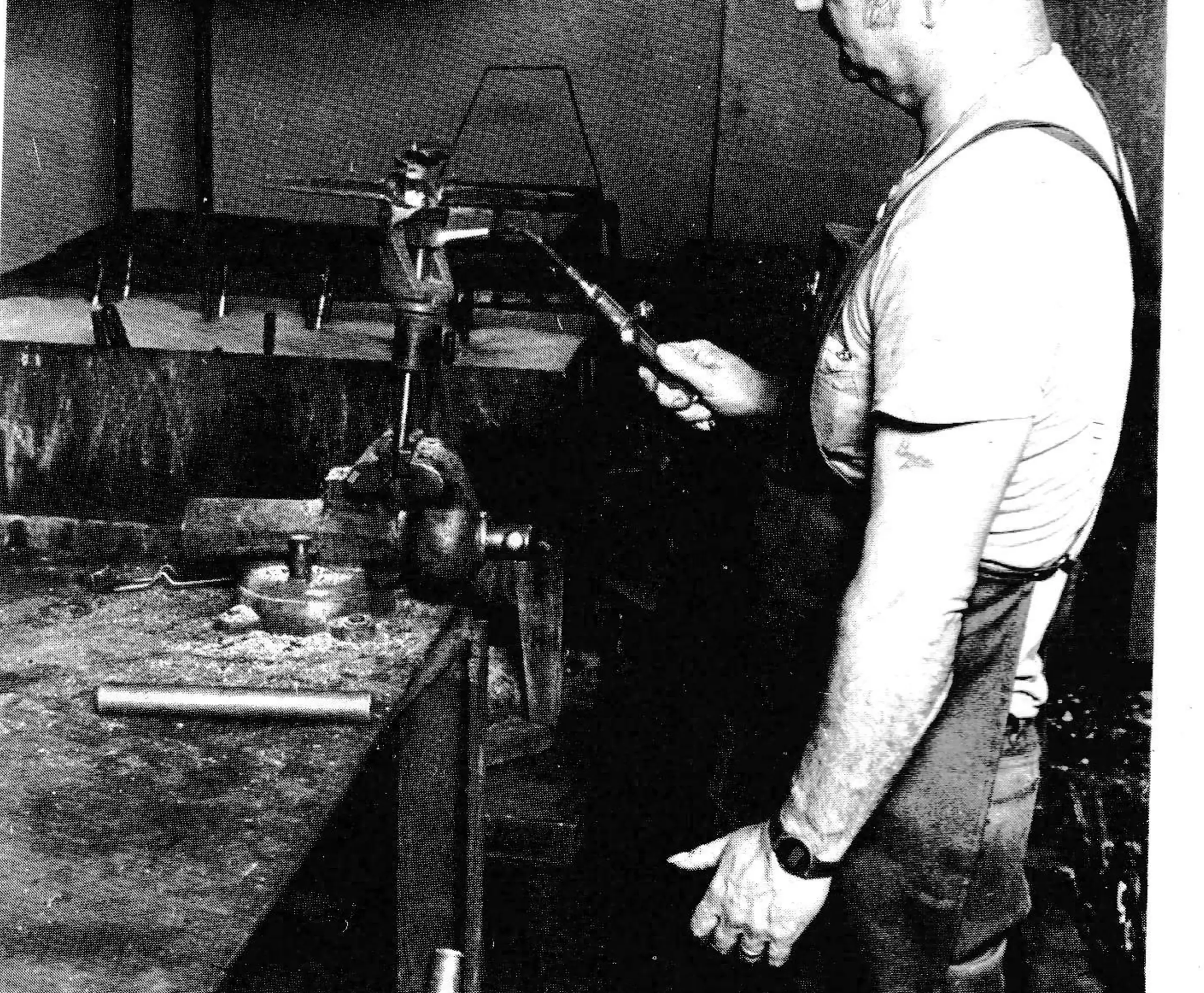
Due to the “removal” recommendation, MT is well suited for detecting possible flaws in chair grips and related parts. The photographs, which were taken at the Hall Ski Lift Company, show the proper procedure for this testing process regardless of whether it is done in the field or shop.
In the next issue of SAM, we will discuss Ultrasonic Testing—method of using sound to determine the location of imperfections in various materials.