

When Vail’s lift boss, Dave Larson, said: “OK Steve, let’s go for it,” I broke into a cold sweat. For over two years, I had been working with Holy Cross Electric Association and Var+Controls, Inc. to correct the harmonic distortion, caused by our SCR drives, on the local power system. Now, I had the go ahead to present a scenario to upper management and get under way. Why was I nervous? I was about to commit the company to spend up to $500,000 on “black magic.” —S.H.
Introduction
Ski resorts typically have numerous DC drives and/or adjustable speed AC drives powering their lifts—today, frequently with 600 to 1,000 horsepower drives for the high-speed detachable quads which are becoming the norm.
These non-linear loads produce harmonic currents which can result in voltage distortion on the utility and mountain distribution systems. This voltage distortion can cause equipment problems anywhere on the system. Computers and programmable logic controllers (PLC’s) are especially sensitive to this phenomenon. The voltage distortion can result in incorrect operation of controls, capacitor failures, motor and transformer over-heating and increased system losses.
Power factor correction is particularly important for DC drives because the phasing back of the SCRs results in relatively poor power factor, especially when the motor is operating at reduced speeds. Additional transformer capacity is required to handle the poor power factor conditions (and the harmonics), and as more utilities are charging a power factor penalty, this can significantly impact the total bill for the facility.
Harmonic Madness
What can happen when electronic gremlins have a go at a utility’s power? Here’s a sampling from the complaint sheets at Vail:
- The food service operation at Eagles Nest couldn’t even open their cash registers, let alone process transactions.
- A noxious pall started to creep over the valley as computers that control the sewerage system failed.
- The Westin Hotel’s telephone system failed daily.
Vail Associates and the utility may have denied responsibility for these and other happenings, but as this article shows, they took more than a casual look at what was going on.
The Standard and the Responsibility
To insure that the voltage distortions on their distribution lines do not exceed five percent, utilities are requiring that their customers manage the harmonic current distortion levels being produced, based on the recommended thresholds set by the IEEE 519-92 Standard. Voltage distortions must be less than five percent, and individual currents must range between two and eight percent, depending on the load and maximum short circuit current.
Utilities do not generate harmonic currents, customers do. It is the responsibility of the customer to maintain current distortions limits.
Characteristics of Drives
All drives have the following characteristics:
Power Factor—A. DC drives operate at a very poor displacement power factor due to the phase control of the SCR’s. Measurements show that a typical drive power factor can range between a 0.60 and 0.80, depending on its speed and load. B. AC variable speed drives, due to the use of a diode bridge converter, operate at power factors ranging between 0.90 and 0.98.
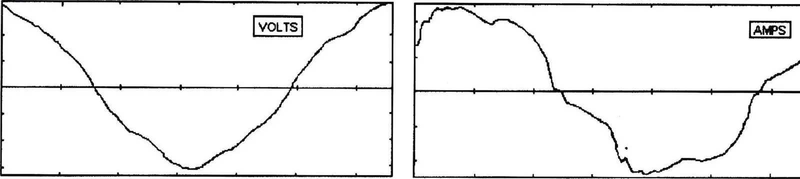
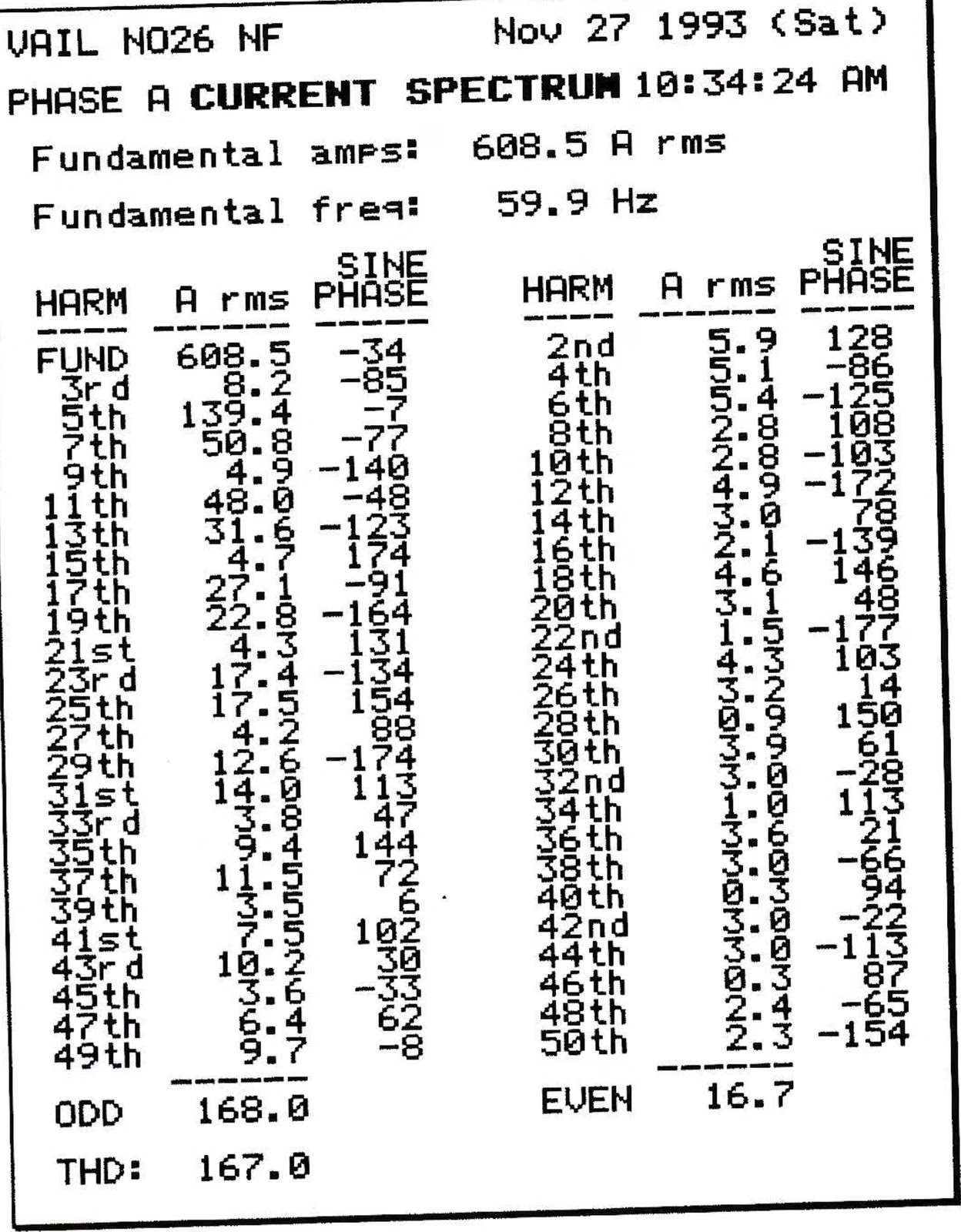
Harmonic Current Distortion—Figure 1 displays a typical current wave form and spectrum for a 700 hp Sabina DC drive. Regardless of the drive type, DC or AC variable speed, these magnitudes of harmonic currents result in a utility voltage distortion level of seven to eight percent. The harmonic currents injected by all of the lifts onto the utility system are well in excess of recommended limits in the IEEE 519-92 Standard.
Utility Problems
In 1990, Holy Cross Electric Association began experiencing problems on their distribution system. Vail Mountain’s 25 lifts, with an aggregate of nearly 8,000 hp, were suspected as the cause; with this in mind, preliminary harmonic measurements were recorded at key sites.
Holy Cross discovered that the Voltage Total Harmonic Distortion (THD) in and around the town of Vail ranged between 6 and 10 percent. The 25 kV feeder, which supplies only the mountain, had current and voltage distortions of 13 and 8 percent respectively. On the mountain, the numbers were even larger. The 1,000 hp Chair #16 lift had a THD of 12.97 percent and a Total Demand Distortion (TDD) in excess of 27 percent.
The IEEE 519-92 Harmonic Standard requires voltage distortions to be less than 5 percent. Obviously there was a problem—actually, there were problems. Holy Cross contracts with their customers to supply them with “clean” power, but because of the levels of harmonic distortion created by Vail’s lifts, Holy Cross’ other customers were beginning to experience their own problems—a condition that had to be corrected immediately.
Possible Solutions
Vail and Holy Cross began researching possible solutions. Harmonics occur anywhere non linear loads are present so this is not a problem unique to the ski industry, it is a problem happening all over the country. The initial solutions leaned toward increasing the size of conductors and transformers—even to installing isolation transformers. These solutions would have been temporary fixes, however, and would have merely applied a band aid to the problem instead of solving it.
Finding a technology partner who specialized in power quality solutions was clearly called for. Enter Var+Controls, Inc., of Whitmore Lake, Mich., designers and builders of custom harmonic filtration and power factor correction equipment. Their main thrust had been primarily with industrial customers such as General Motors, Ford, Honda of America, Kellogg, Borden Products and other industrial companies, large and small.
The initial approach was actually through a “cold” sales call. “Every time I skied at, or drove by Vail,” recalls Bill McConnell, the marketing director, “I said to myself that with all of those DC drives they must be experiencing some serious harmonic problems.”
The ski industry would present an interesting challenge.
Developing a Plan
Each lift at Vail has its own dedicated transformer and utility meter. Since Holy Cross was treating each lift as a separate, stand-alone entity, a preliminary proposal was presented to Vail and Holy Cross distribution system into compliance with the IEEE 519-92.
However, there were some major concerns with this approach:
1) Cost—The equipment and installation costs of installing between 20 and 25 filters would have been exorbitant;
2) Installation Time—Not all of the filters could have been installed in time for the next season. Therefore, the project would have to have been spread over two seasons;
3) Filter Overload—During the first season, with only half of the filters online, there would have been the potential for premature filter failure. Each installed filter would have tried not only to absorb the harmonic currents being produced by its drive but also from the other non-filtered drives as well. This did not seem to be a viable solution.
At a meeting in April 1991 of Vail, Holy Cross and Var+Controls, it was collectively decided to view Vail and Beaver Creek mountains as single circuits as opposed to a combination of many individual circuits. By doing this, the harmonic content of each mountain could be reduced (managed) by installing fewer strategically sized and placed harmonic filters. This approach also afforded Vail the flexibility of not always having to add filters for every future lift or drive upgrade.
Systems Approach
Now that Holy Cross was willing to treat Vail and Beaver Creek as single circuits, a systems approach could be implemented in the design of the equipment.
- During the 1992 season, Var+Controls recorded the harmonic spectra for all lifts greater than 100 hp at the Vail and Beaver Creek operations.
- Richard Brinkley and John Spangler of Holy Cross were recording similar data at their sub-stations and at other key locations along their distribution system.
- With the assistance of Electrotek Concepts, Var+Controls, built computer models of the utility and mountain distribution systems, enabling simulations to be run using different tuning frequencies, quantities, sizes and locations of filters.
In April of 1992, Var+Controls presented the final proposal to Holy Cross and Vail, based on computer simulations that showed the placing of five filters at Vail and two at Beaver Creek would bring Holy Cross’ distribution system and main substation into compliance with the IEEE 519-92 harmonic standard.
The filters were configured and designed to absorb the fifth and seventh harmonic currents. Since the seven filters were required to absorb the harmonic currents of their respective drives, as well as the currents from the other non filtered lifts, 600-volt capacitors, de-rated to 480 volts, and single phase iron core reactors were specified.
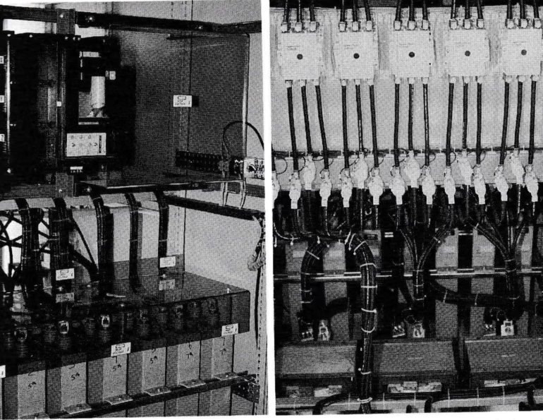
In any passive filter design, as shown in Figure 2, the capacitors and reactors are connected in series. As the harmonic currents flow through the reactor, a voltage, current and kVAr rise across the capacitor occurs which may exceed the capacitor’s designed duty limits. Failure to recognize these capacitor limits will result in premature capacitor failure.

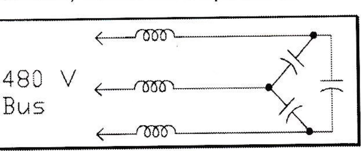
The combination of 600-volt capacitors, along with properly sized single phase reactors, will avoid this problem.
Since Vail was planning on adding another quad detachable on Vail Mountain in the summer of 1993, it was decided to install an additional filter at this drive to further reduce the harmonics on the mountain. Vail Associates and Holy Cross duly approved the concept of installing six filters at Vail mountain and two at Beaver Creek during the summer of 1993.
Project Funding
For a project of this magnitude, funding is a very important factor, and it was clear that the customer and utility must work together to solve power quality problems.
Holy Cross was concerned with the quality of their power, since they were out of compliance with IEEE 519, and as Vail was a main contributor to this problem, it was concluded that both parties had to work together to solve each other’s problem.
Since the Holy Cross rate structure penalizes customers whenever the power factor falls below a 0.95, and with Vail’s average power factor ranging between a 0.77 and a 0.80, the energy penalty worked out to nearly 15 percent.
Vail and Holy Cross executives devised a financial package that would allow Vail to pay for the project through the savings they would realize by improving their power factor. An interest-free, six-year note, payable to Holy Cross in monthly installments, was signed by Vail.
Benefits Summarized
- Their operating costs will not increase due to the acquisition of the filters.
- They will retain ownership of the equipment and thereby gain the tax advantages.
- After six years they will realize the savings on the energy bill as a result of the improved power factor.
Installation
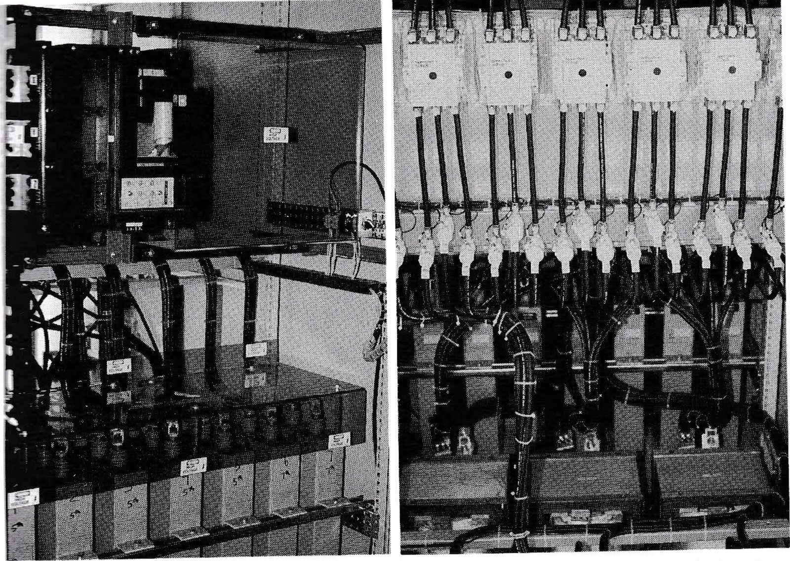
In August of 1993 all of the units were installed at Vail and Beaver Creek mountains. All systems were 464 kVAr tuned to the 5th and 7th harmonic.
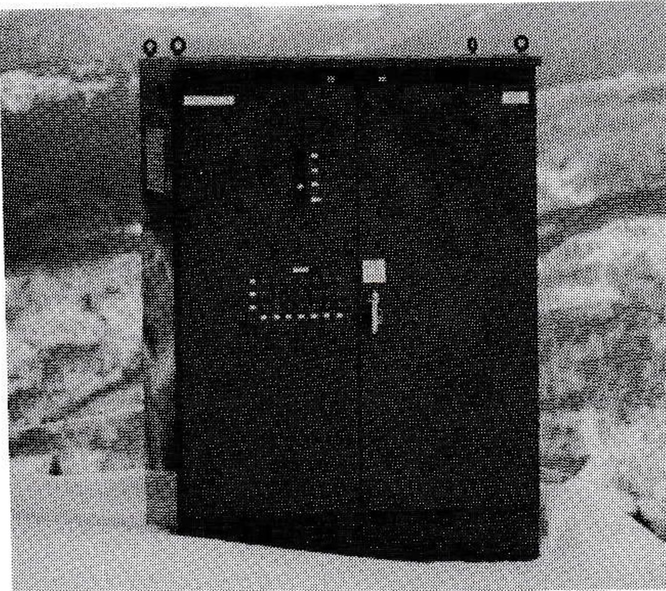
Seven of the systems were housed in free-standing Nema 3R enclosures which were set on concrete pads next to the Holy Cross transformer. The eighth unit was configured to match the Sabina drive cabinets and low voltage switch gear. It was installed in the lift house of the new CTEC detachable chair lift.
Startup and Field Testing
In September of 1993 Var+Controls, with Holy Cross and Vail personnel in attendance, energized the systems and conducted preliminary testing. Though the initial data indicated the filters were performing as designed, there was no load on the system, so additional testing was required over the Thanksgiving weekend. At that time, harmonic measurements were recorded by Var+Controls at all filter locations. The filtered lifts were loaded but the entire mountain was not fully operational.
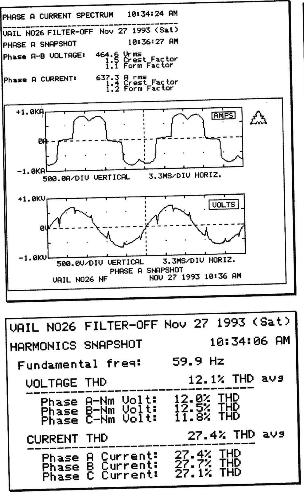
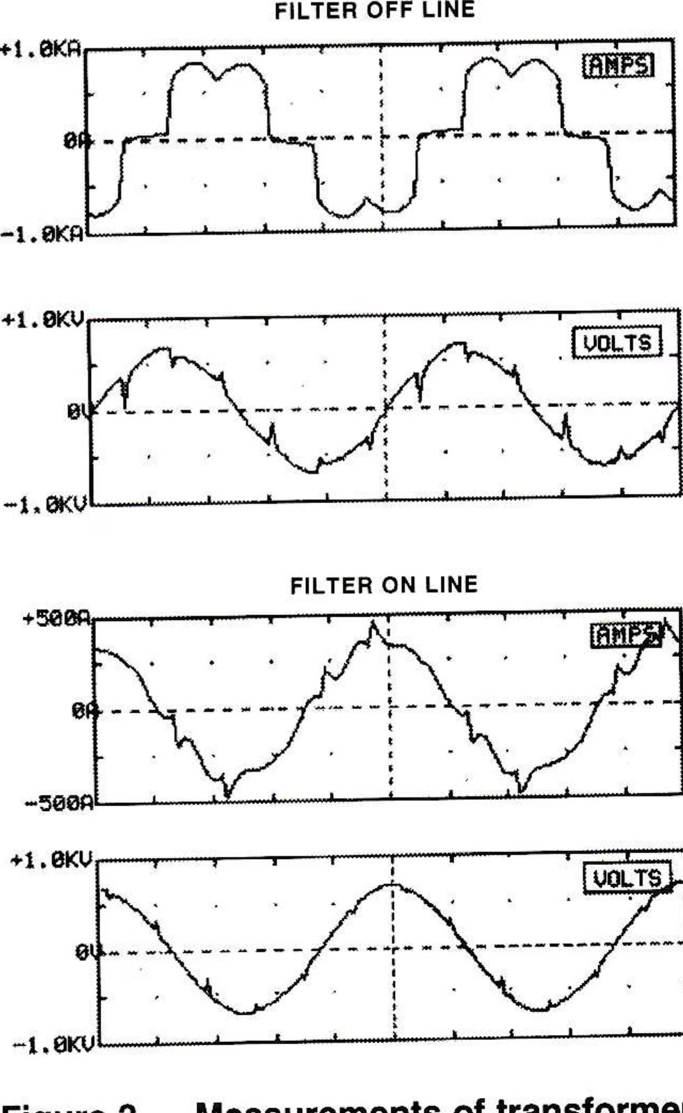
To everyone’s relief, the filters reduced the harmonic distortions at each lift to below the IEEE 519-92 thresholds. The filter performance measured at the 1,000 hp chair #16 transformer, can be seen in Figure 3.
Additional tests were performed at the drive cabinets by Vaughn DeCrausaz, of Starboard Electric, to study the effects of harmonic distortions on the performance of the drive. (Starboard Electric is the authorized Colorado sales and service representative for Sabina Drives.)
The testing revealed that the harmonic distortion and notching of the wave form at the drive can cause problems in several areas. The armature current feedback circuit is of a very small signal level (50 millivolts for 100 percent current) and is susceptible to any harmonic noise in the drive cabinet that causes nuisance motor trips from over-current as well as erratic acceleration and deceleration. In addition, the regulated field supplies have been found to regulate at an improper level, or not reduce the fields at the correct armature voltage (crossover) with harmonic distortion on the power supply.
This will cause improper speed regulation, erratic acceleration and deceleration, or too high armature voltage, in turn causing possible commutator flashing.
With the filters on-line, these problems virtually disappeared.
Full-load Verification
The final checkout for the results of three years of work took place December 30, 1993 when test equipment for monitoring was set up at the Vail/Beaver Creek substations. On hand were representatives from the Holy Cross Electric Association, Inc., Var+Controls, Public Service Co. of Colorado, Starboard Electric, Inc. and Vail Associates.
Figure 4 shows the voltage and current wave forms with the filters off and on.
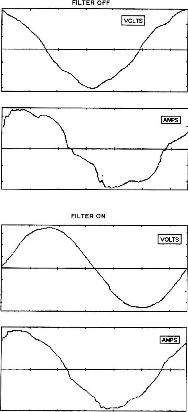
With the mountains fully loaded, Holy Cross mountain circuits were brought into compliance with the IEEE 519-92.
Everybody was a winner that day!
Summary
Harmonic filtration projects at ski areas require a coordinated effort between the customer, utility company and equipment vendor. The projects are very complicated and should not be hurried along to meet any arbitrary deadlines. To insure project success a Systems Approach should be implemented which uses computer modeling to aid in the design of the equipment.
Once a mountain has been brought into compliance with IEEE 519-92 or with the requirements of the servicing utilities, the future installation of non-linear loads and/or capacitors (both high and low voltage) should not be undertaken without first analyzing the impact these devices will have on the harmonic profile of the mountain.
The equipment vendor should be selected based upon an ability to perform:
- On site harmonic and power data acquisition;
- Computer modeling of the distribution system;
- Hardware design;
- Hardware manufacturing;
- System start up; and
- Harmonic verification measurements under full load conditions.
As a result of this project, Holy Cross Electric is considering changing its power factor billing practices to a totalized billing system on Vail and Beaver Creek mountains, instead of from a reading and penalty for each lift. This change will further reduce the monetary penalties for power factor faced by Vail Associates.
References
- [1] Revised Standard IEEE 519, “Recommended Practices and Requirements for Harmonic Control in Power Systems,” Approval June, 1992.
- [2] T.E. Grebe, M.F. McGranaghan and M. Samotyj, “Solving Harmonic Problems in Industrial Plants and Harmonic Mitigation Techniques for Adjustable Speed Drives,” Electrotech 92 Proceedings, Montreal, June 14-18, 1992.
- [3] M.F. McGranaghan and W.C. McConnell, “Power Factor Correction and Harmonic Control for DC Drives Loads,” PCIM Conference, September 1991