


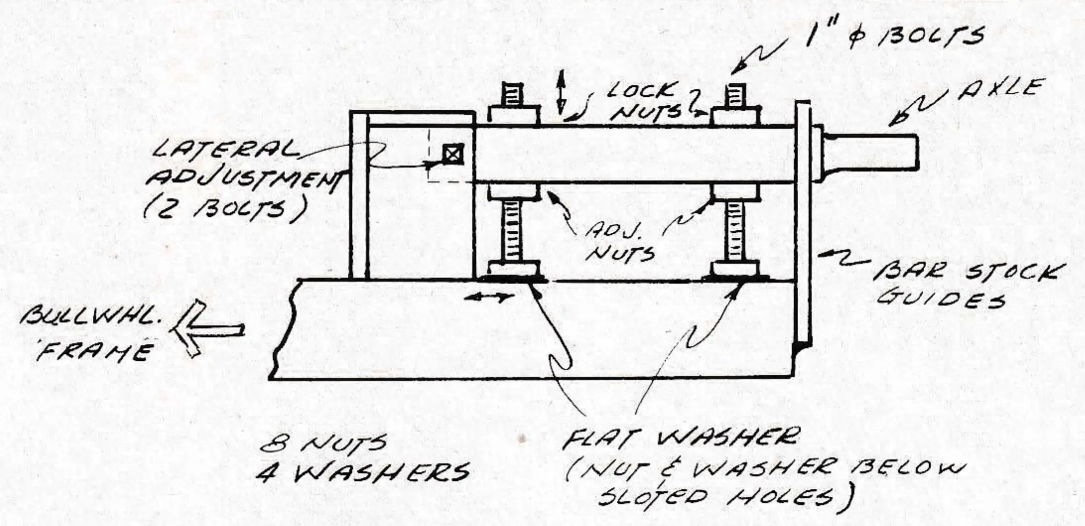
Guide sheave adjustment
A frame work is placed around the sheave axle which is mounted on two 1-inch bolts. Adjusting nuts are placed below the axle while locking nuts are placed above the axle. Two locking set screws are placed near the in board end of the axle for twist adjustment. The 1-inch bolts are in slotted holes in the arm for in and out adjustment.
Chair clamp relocation
In January, the Canada West Ski Areas Association held a Maintenance Seminar at Grouse Mountain. SAM is pleased to present some of the best ideas that came out of this seminar in this and subsequent issues.
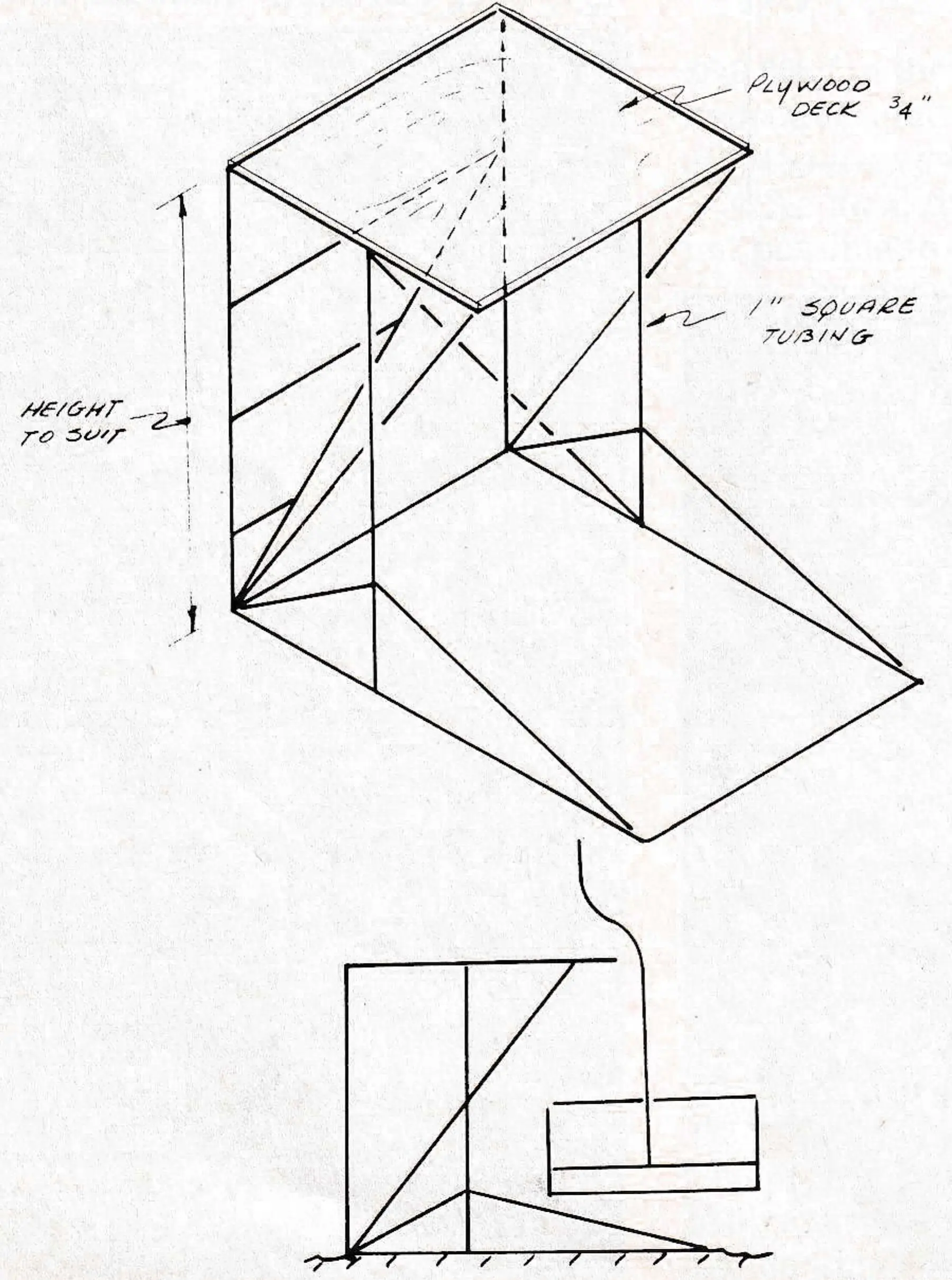
We start off with one from Harvey B. Fellowes, Assistant Manager (Operations) for Garibaldi Lifts, Ltd., Whistler Mt., who has solved the problem and relocation of chair clamps. They built a portable, chair lift scafold.
This stand enables the mechanic to work at a comfortable level where it is easy to maintain chair clamps. The chairs will pass by the stand without having to move it away.
Timely advice
Jim Gardner, of Valley Engineering passes on this warning to owners of grooming attachments. Most hydraulic cylinders are easily removed by vandals and seem to be very popular on homemade hydraulic wood splitters. Pack them away this summer in a safe place.
How long is a rope?
Bob Diener of Vail, our expert on rope splicing, rigging and trouble shooting, gives these thoughts on how to calculate the length of your wire rope if you don’t have records.
How long is the wire rope on your chairlift X?
The obvious answer is “twice as long as half,” half being the length of the lift. Well, this is O.K. if you are prepared to order an extra 500 ft. or so just to be sure or, you can dig out the invoice for the last rope you bought and then try to remember the length of the remnant that was cut off of one or both ends. You can consult the design prints, but they usually don’t tell you precisely at what point or points from which the lift is measured or where the tension carriage was when the rope length was calculated.
At best the length cannot be determined without a considerable amount of research. I would venture to say that even the most competent engineers would be wary, after calculating the sags and the elastic stretch, of guaranteeing an estimated length to within a 25 foot tolerance.

What difference does 25 or 50 feet make? Not much if it’s on the long side, but it’s hell if you’re short. It has happened.
How about chair spacing? Some areas, for instance, have their chairs spaced at 50-foot intervals or less. A rope length-chair-spacing error would be quite conspicuous when that last chair was hung, not to mention the embarrassment to the well-meaning mechanics who did the job.
The length of the rope is important. It should be known to the nearest foot and recorded in the rope log together with an exact location of the tension carriage. The lift designer should provide you with that information when he installs the lift, but in case he forgot, you can still determine the rope length. There’s more than one method of determining the rope length. There’s more than one method of determining rope length, but here is how I do it.
First off it is pretty well accepted that a bull wheel revolution is the most practical and accurate guage available to us, so we’ll use it. These are the steps:
- Run the lift a few minutes to free things up, especially if it has been standing idle.
- With a crayon (Markall ‘B’ is fine) sharpened to a good point, place a bright, narrow mark on the bull wheel liner and a corresponding mark on the cable.
- Run this mark out of the bull wheel and in the clear where you can get to it with a ladder. Using just enough electrician’s tape, tape the end of a 50 or 100 foot steel measuring tape to this mark. Take note of exactly where on the mark the zero end of the tape is and secure it well enough so that the measuring tape can be pulled tight, but not so well that it can’t be pulled off with a long steady pull. It should be on the under side of the cable so that it will not foul in the depression sheaves.
- Now run the lift far enough to get a repeat mark on the cable using the bull wheel liner mark as a reference. Now run again to put cable mark 2 at the ladder point where the man on the “smart end” of the tape can pull it up tight and read to the nearest 1/8 of an inch. Record the reading and, with a long steady pull, pull the zero end of the tape loose.
- Repeat steps 1 through 4 at least three times and take the average of all the readings. You now know the length of rope each bull wheel revolution will pay off.
Remember, if you have an error it will accumulate 200 to 400 times or however many turns the bull wheel makes in one complete cycle of the lift cable. This can really add up. - Now place a filament tape band mark on the cable, referenced to a fixed member of the lift (not the bull wheel) and a good, easy-to-see mark on the bull wheel. It’s a good idea to use 4 to 6 ft. long ‘coming’ and ‘going’ stripes relative to the “count” marks. This is in case the counter man blinks his eyes or sneezes and misses it.
- Take note of the precise location of both the cable band mark and the bull wheel mark, give your counter man a scratch pad and make him comfortable, start the lift and run full bore until the cable mark returns. Remember it’s easy to lose a count or two so keep the tourists away from the counter and don’t talk to him. If there is any doubt about the count do it again.
- Stop the cable band mark as near as you can to the starting point. Now, after multiplying the number of bull wheel revolutions by the number of feet each one represents, you will have two corrections to make: one for how far the cable band mark is from the starting point and one for the nearest complete revolution of the bull wheel. Either can be an addition or subtraction depending upon how you stopped.
You now know how long your cable is. You can forget about the extra length in the sags between towers. You can forget about elastic stretch and temperature variations. You only need to know how many feet of length are in the spliced cable with the counterweight in suspension and where the tension carriage was when you measured it.
Because this is an endless cable there is no zero point. To each chair belongs one chair length, so divide the total length by the number of chairs and you have it made.