

One of the major components of any lift drive system is the unit that reduces the speed of the motor or engine to the slower speed of the drive sheave (bull wheel). For example, a typical lift may operate at 500 feet per minute, and have a 10-foot bull wheel. If driven by a conventional electric motor that has a rotational speed of 1750 rpm, this lift would require a speed reduction of 110 to 1. (Table I presents the total speed reduction required for typical electric motor and diesel engine drives with different sizes of bull wheels. See next page.)
Because of the large reduction required, nearly all lift drives incorporate an enclosed gear reducer in the drive system. This reducer can be used in one of three general ways.
In Figure 1A, the gear reducer performs the complete task of speed reduction. Motor (or engine) power is connected to the input shaft at high speed. A series of gear reductions within the reducer brings down the speed. As a result, the output shaft turns at the desired lower speed.
In Figure 1B, an open ring gear is attached to the bull wheel. The gear reducer has a pinion which is mounted on the low-speed output shaft and which meshes with the ring gear. As in case 1A, the input shaft of the reducer turns at motor or engine speed.
In Figure 1C, a V-belt drive has been added between the motor or engine and the reducer input shaft, reducing still further the degree of speed reduction required of the gear reducer.
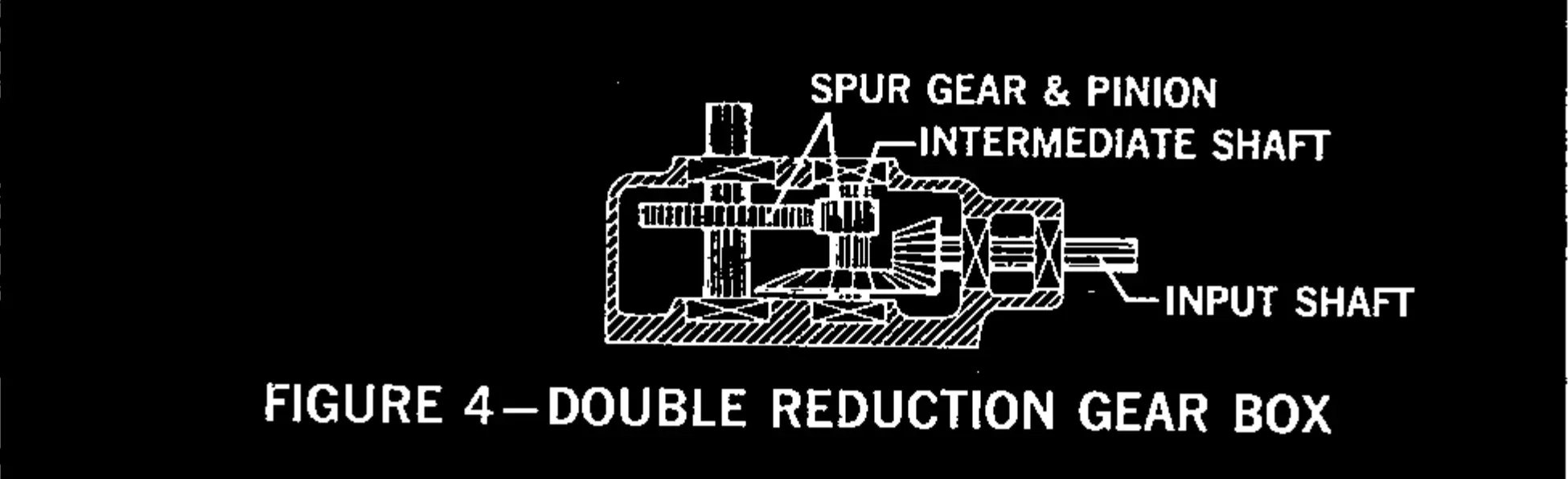
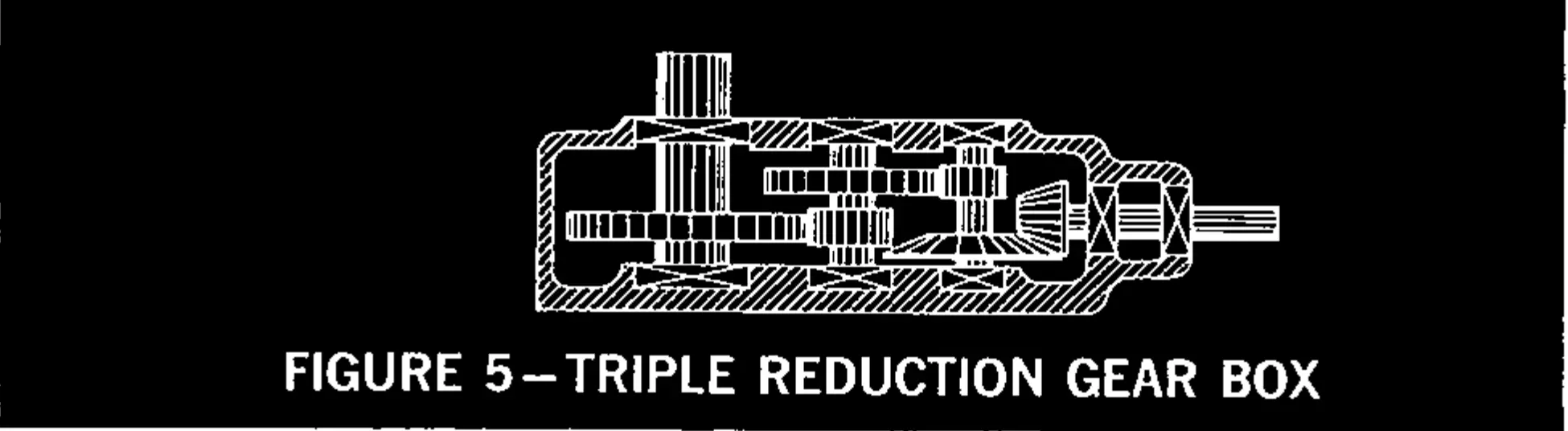
In practice, the amount of speed reduction that may be successfully obtained with only one set of gears (worm gears excluded) is limited to a value below 10:1. Thus, in case 1A, where a total reduction of 110:1 is required within the gear reducer, three sets of gears must be employed to achieve the total reduction. This is known as a triple reduction gear reducer. In case 1B, two sets of gears are required and this is a double reduction unit. Case 1C requires one set of gears, and is a single reduction unit.
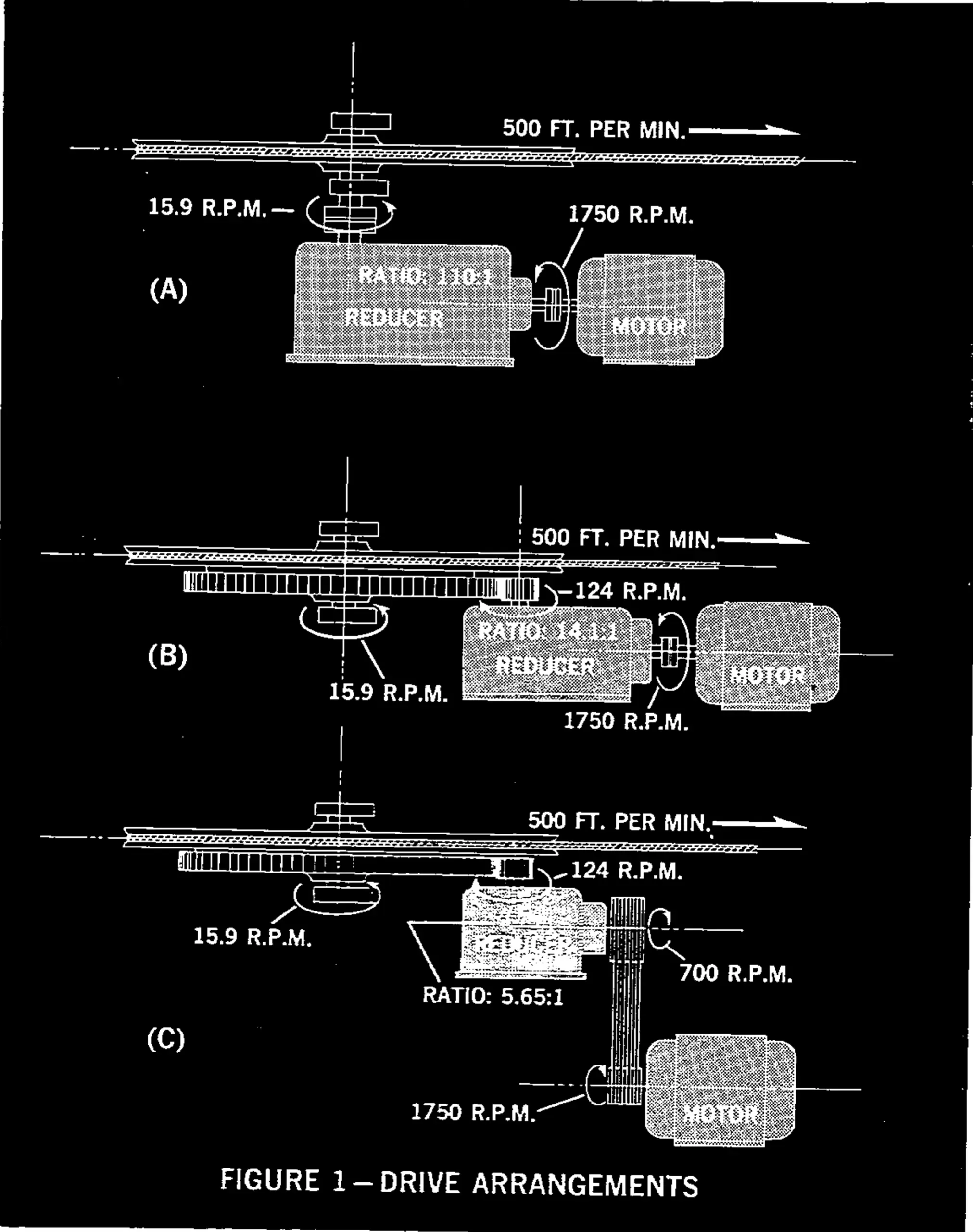
When all three drive arrangements are reviewed, it can be seen that in actuality, all systems have three stages of reduction. In case 1A, all reduction stages are within the reducer. In case 1B the final stage is the external ring gear-pinion. And in case 1C, the third stage is the ring gear unit, the first stage is the V-belt system.
Parallel and Right Angle Reducers
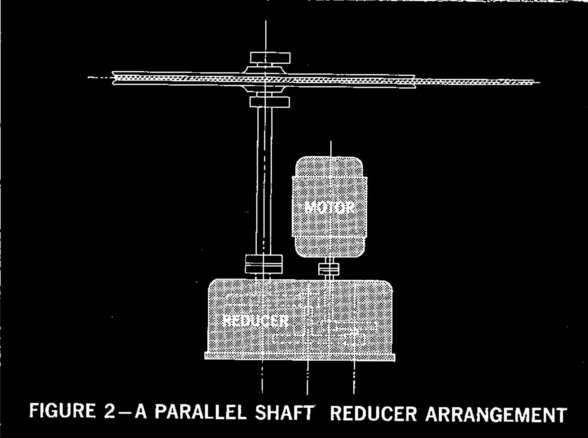
Gear reducers can be divided into two general types. One type has a parallel shaft arrangement, where the input shaft and the output shaft are parallel to each other. In this arrangement, the input shaft may enter from the one side (on top) of the box, the output shaft may exit from the opposite (or bottom) of the box, or both may be located on the same side of the box. The direction to power transmission cannot be changed by a parallel shaft arrangement. Gearing within this type of box is usually of the spur gear class. In a normal lift arrangement, the bull wheel shaft is vertical. Therefore the use of a single parallel-shaft gear reducer requires that the motor driving the lift be mounted vertically (see Figure 2).
| Bull-Wheel Diameter (ft.) | 8′-0″ | 10′-0″ | 11′-0″ |
|---|---|---|---|
| Bull-Wheel R.P.M. | 19.9 | 15.9 | 14.5 |
| Total Reduction with 1750 R.P.M. Electric Motor | 88:1 | 110:1 | 121:1 |
| Total Reduction with 1200 R.P.M. Diesel | 60:1 | 76:1 | 83:1 |
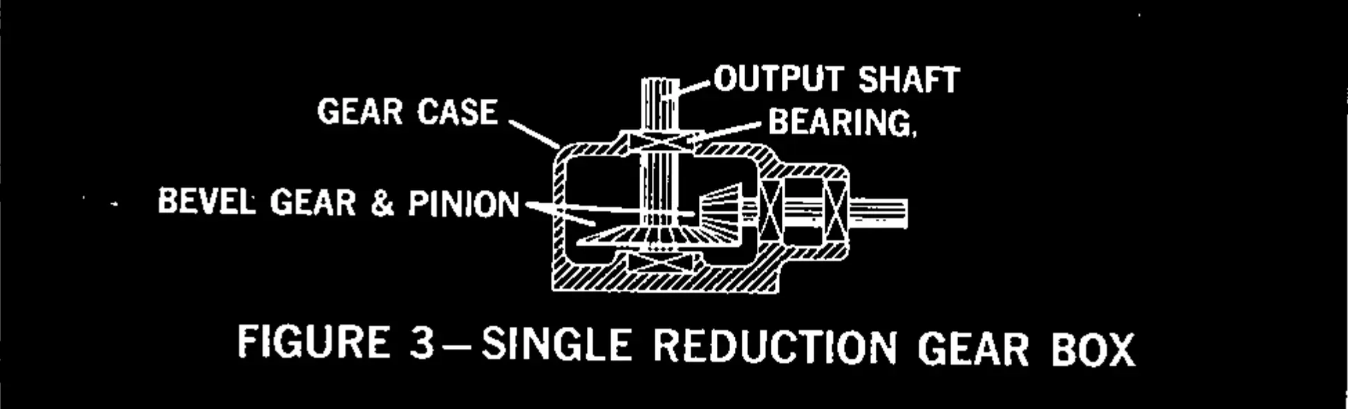
The other type of gear reducer has a right-angle arrangement. Here the input and output shafts are arranged at right angles to each other. In order to achieve the right angle change-of-direction, two methods of gearing normally are used—worm gears or bevel gears. Of the two methods, the bevel gears are the more efficient (and costly), since the worm gear requires sliding motion between the worm and the worm-gear. Bevel gears can be either straight teeth or spiral teeth. The latter have greater load-carrying ability, and wear less. Greater reduction ratios can be obtained with worm gears. But as the ratio of a single worm arrangement increases, the efficiency decreases. This reduction in efficiency is accompanied by an increase in heat output by the gear box. Thus a worm reduction unit often is provided with exterior fins and occasionally a fan to aid cooling. Often a large right-angle reduction is successfully accomplished by using a low-ratio worm reduction to achieve the right angle change-of-direction. Additional sets of spur gears obtain the total reduction.
Principal Components
In all reducers, there are three primary types of moving components: 1) Gears (and pinions); 2) Shaft; 3) Bearings.

Gears, in order to operate with assurance of long life and minimum friction, must be correctly aligned, and they must maintain this precise alignment under all conditions of loading. This requires that the shafts supporting the gears be sufficiently large so as to prevent excessive deflection, and that the bearings be so mounted that the alignment is maintained. In addition to supporting the gears, the input and output shafts and bearings must also be capable of withstanding external loads applied by the driving equipment. For example, in Figure 1C, the reducer input shaft is subjected to a downward load due to the tension and pull of the V-belts, and the output shaft is subjected to a horizontal load due to the pressure of the external pinion teeth against the gear teeth of the sheave-mounted ring gear. All of these components must be mounted in a box that is sufficiently strong to transmit these loads through the shafting and to the mounting bolts.
Lubrication
Two general methods of lubricating the gears and bearings are employed. The first method is known as the “splash-feed” method. Here a reservoir of lubricant is provided in the bottom of the gear box. At least one gear dips into this lubricant and splashes it around the interior of the box to the bearings and other gears.
The second lubricating method is called the “force-feed” system. Here a pump receives lubricant from the reservoir and pumps it to the bearings and gears. The lubricant pump may be driven by one of the shafts within the reducer, so that it pumps only when the reducer is running. The speed of the pump is related to the speed at which the reducer is operating. With this arrangement, there will be a short delay, upon starting, before lubricant under pressure is at all bearings and gears. The lubricant pump may also be driven by a separate motor. Here the pump will operate at constant speed regardless of the speed that the reducer is operating. It can be started prior to the start of the reducer and obtain lubricant circulation prior to the movement of the gears. Normally an oil pressure gauge is provided in the “force-feed” system.
Other Accessories
The most important operating problem for a reducer is the extreme low temperature to which the unit may be exposed. A reducer suffers the same cold weather problems as an automobile garaged outdoors overnight and called upon to start in the morning. Exceptional internal loads can be imposed on a reducer when an attempt is made to circulate the lubricant, at extremely low temperatures. Thus provision for a “garage” (drive room) for the reducer is desirable. Where such protection from cold weather is impractical, the use of special heaters to heat the lubricant is desirable. Electric immersion heaters can be installed directly into the reservoir.
Cold temperatures can also result in the condensation of water within the reducer. The manufacturer’s oil change recommendations should be followed to keep the effects of such condensation to a minimum.
Failure of a gear reducer during the operating season can result in a major repair job and great loss of operating time. Thus the cost of following recommended care of the unit is minor compared to the disassembly of a gear reducer to replace a simple bearing.
Often a failure, even under thorough care, will occur. However, bearing failures can often be spotted well before the final failure occurs by a tell-tale noise. Operational personnel should be constantly alert for strange sounds coming from the gear box. Because a reducer is a compact, totally enclosed component of a lift drive system, it is often ignored for year after year. It requires but minimum attention.