

It’s been somewhat of a problem for me to write on inspection reports that the gauge alignment of a tower should be corrected and not be able to explain it to the operator, even though the haul rope may be running somewhat down the center of the sheave groove. Then came the term gauge alignment which still is not understood by a great many people, even though it is important.
Mr. Cooper further did a nice job in giving it a definition: “An invisible line that extends from the tangent point of the lower bullwheel, uphill to the corresponding tangent point of the upper bullwheel. There are two of these gauge lines. One on the heavy side of the lift and the other on the light side.”
My dictionary further defines gauge as follows: “A carpentry tool for marking lines parallel to an edge . . . and further among other definitions, “a standard Measure.”
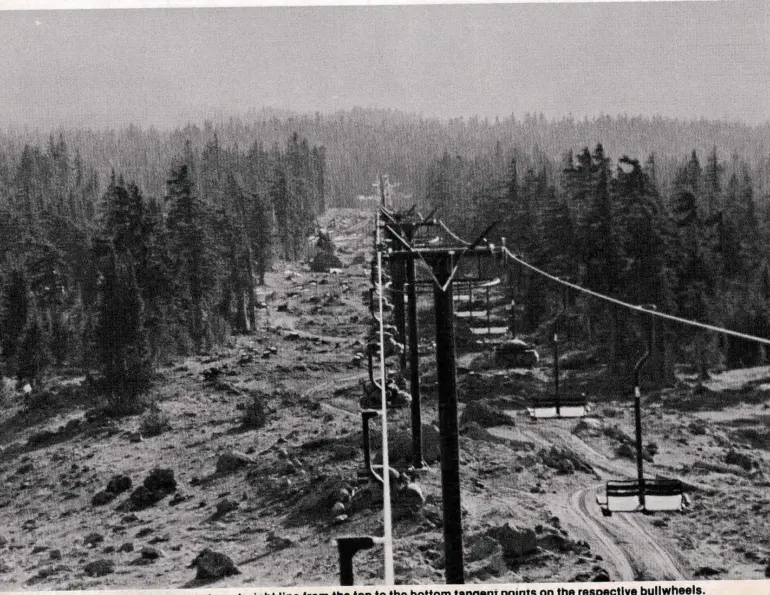
They say a picture is worth a thousand words so behold the photo which shows, among other things, a haul rope in a very straight line between the top and bottom tangent points of their respective bullwheels. In this photo the haul rope is following the exact path an invisible line would take between the tangent points of the top and bottom bullwheels. Therefore this photo shows good gauge alignment on one side of the aerial facility, remembering there are two gauge lines on a chairlift.
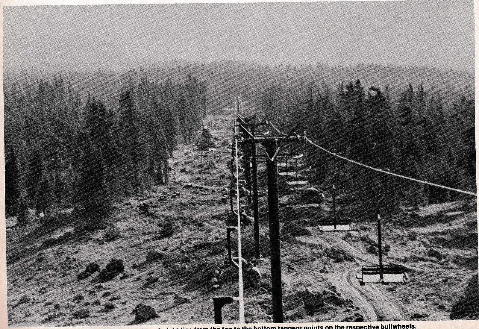
Gauge misalignment can occur when lift towers are hit directly with an avalanche. I call this excused gauge misalignment. In such cases you may see misalignment of seven inches or more on the down or up side of the lift.
What is bad gauge alignment? This has not been defined so I will merely state the following. If a sheave is sitting either to the left or right of that imaginary invisible line, the gauge alignment is bad, or incorrect. How much can actually be tolerated is up to the manufacturer to actually specify, so you may want to contact your manufacturer or area engineer.
I have both seen and written reports designed to correct problems where the sheave or tower has been out of gauge alignment by up to about 18 inches. This occurred on a set of depression towers in a hole and they were difficult to get a good fix on. They have now been corrected.
Some causes of poor gauge alignment are:
- snow creep, causing the tower and sheaves to move laterally to the right or left, sometimes downhill, and sometimes over;
- error in initial construction;
- soil or foundation problems, causing the tower to shift laterally;
- replacement of tower machinery using different component parts and not getting the sheave frame back at that very exact spot in space;
- tower being hit with a moving object such as a roller, snow cat, or one large boulder (skiers don’t count);
- chairs being caught in the messenger cable have sometimes accounted for this problem.
Refer to illustration A where I have shown a bottom bullwheel, a top bullwheel, 4 towers, and two sets of guide sheaves. Let’s go through this drawing step by step and we will try and cover what we have discussed here.
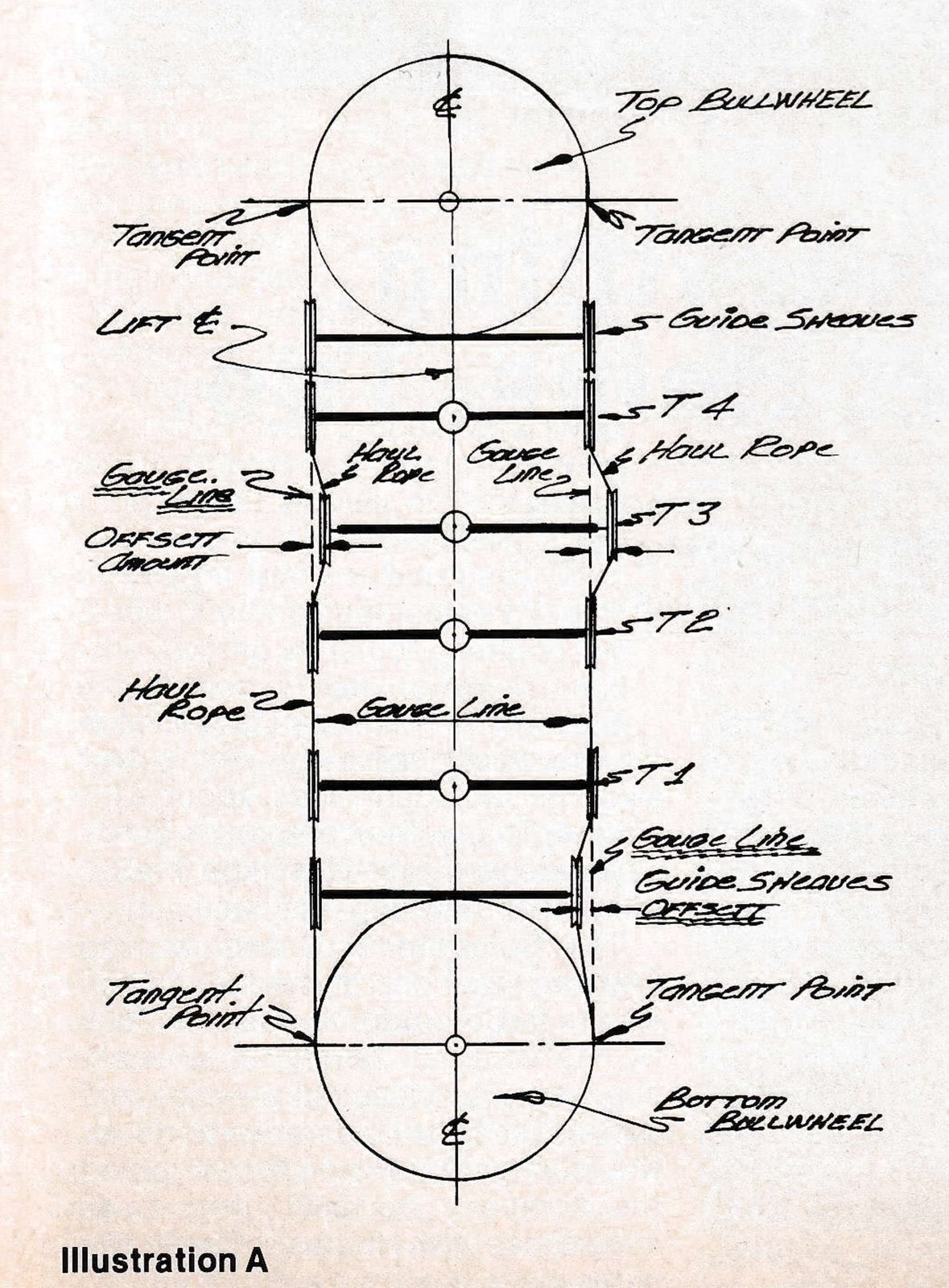
First, on the upside and down-side I have drawn with a dashed line the so-called invisible gauge line which we have said is a straight line between the tangent points of the top and bottom bullwheels.
Second, I have drawn a heavy line to represent the haul rope’s actual position as may actually exist in the field.
You will note that towers Number 1, 2, and 4 sheave frames are in perfect alignment, along with the guide sheaves at the top bullwheel.

Showing poor gauge alignment are: 1) the guide sheave on the up-side at the bottom bullwheel; and 2) tower 3, which shows the sheave to be to the right when looking uphill of the proper invisible gauge line.
The amount of offset of the haul rope at a tower from the gauge line is the amount of gauge misalignment.
Now we have the pesky little critter under control, and now every maintenance person can look up the hill and say, “Ha ha, it’s out to the left, shove it back in and were done.”
Let’s remember that our eyeballs are one of the best preventive maintenance tools that we have, but let’s get out the transit and do a good job of setting things where they were intended. There are some area operators around the country who have developed very good, precise procedures for checking gauge alignment with a transit; however they always try to find out Why It Got The Way It Got. A very important procedure.
In the above discussion you should not forget what I call variable gauge equipment.
Ski Lift International designed lifts with say a 10 foot diameter bullwheel and 11 feet between haul ropes along the line. Therefore the gauge width of the BW is 10 feet and the gauge width of the line is 11 feet variable gauge equipment. (See illustration B.) With variable gauge equipment one needs to “bend” the haul rope. Usually this is done at Tower 1, 2 or 3, depending on spans, etc. To make this bend, one needs to cant or tilt the sheave train to deflect the haul rope in a horizontal bend.
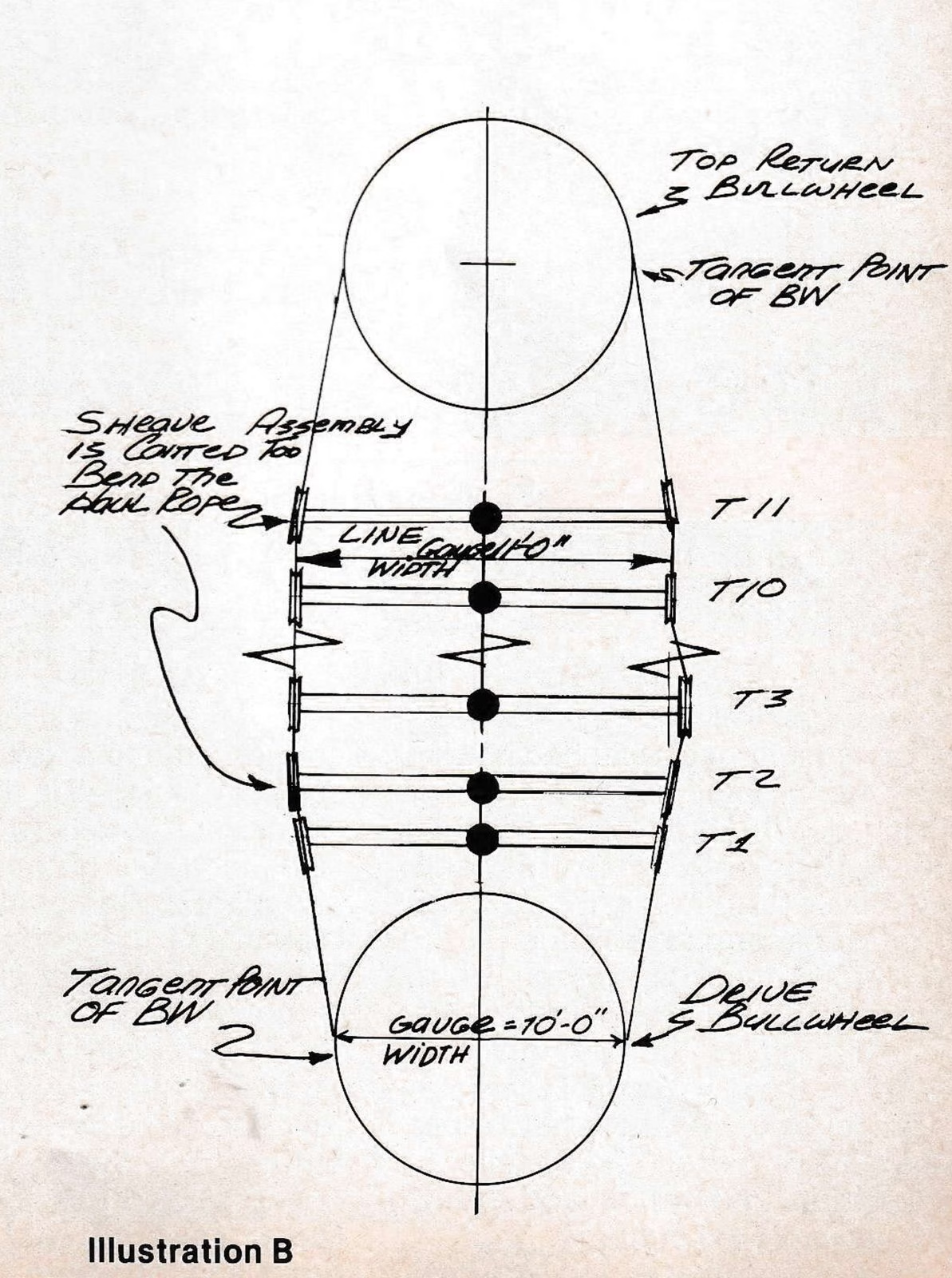
Gauge alignment on illustration B can only be checked within the following areas:
- drive BW tangent point uphill to tower 2, also on down side.
- tower 2 too Tower 11, both sides.
- tower 11 too the tangent point of the return BW.
You will note that a horizontal bend is made in the haul rope on both the up and down sides at tower 2 and tower 11.
Incidently, maintenance people who say that so and so ski area is running a lift with a canted sheave train (tilted), should look again. What they are seeing is a haul rope with a horizontal bend.