

When people in the ski industry discuss pump systems, they are talking about a matched set of mechanical and electrical components. These include pumps, motors, starters, piping, instrumentation and controls. Working together, they should efficiently pull water from its source, boost it to operating pressure, and get it up the mountain as quickly as possible. But that’s just the beginning.
An ideal pump system should maintain constant discharge pressure across flow rates ranging from thousands of gallons per minute to comparative trickles. Such versatility prevents pressure surges and water hammer from damaging pipes and components.
To increase efficiency and reliability, multiple pumps and motors are better than single pumps and motors. They spread the workload, provide backup and efficiently handle a wider range of flow rates.
A well-designed pump system should also automatically maintain constant pressure, detect problems and protect its components. If equipment fails, controls should offer several methods of “back-up” manual operation.
Finally, this system should be compact, energy efficient, fully integrated and have a layout that’s as unobtrusive on the surrounding environment as possible.
Controls
Controls on most snowmaking pump stations are “conventional” because they have pressure reducing control valves, bypass valves and fixed speed pumps.
Pressure reducing valves maintain constant discharge pressure by opening and closing a diaphragm based on feedback from downstream pressure sensors. If this doesn’t adequately lower pressure, a separate bypass returns water back to the source.
Such systems are only efficient when the diaphragm is totally open. Otherwise, substantial pressure drops occur across the valve, wasting expensive energy. Some snowmaking managers have even expressed concerns that heat builds up around partially open valves and raises water temperatures.
The water is pressurized by fixed-speed pumps which run at a set number of RPMs. Although such pumps offer simplicity, they can only provide optimum performance at a specific flow rate per pump. Anything under those flow rates represents wasted energy.
To increase the number of optimum design points, pump system designers often add more pumps and motors. Thus, a system with two identical pumps has two optimum design points: When the first pump is running alone, and both pumps are running together.

The main shortcomings of conventional systems with control valves are inefficiency and mechanical complexity. When demand changes, the pumps are more prone to cycling on and off. This stresses all the components, shortening their lives and increasing maintenance. Systems with control valves also usually require a larger pump house and more complex mechanical infrastructure. Plus, part-time employees are more likely to have problems with such equipment because it isn’t completely automatic.
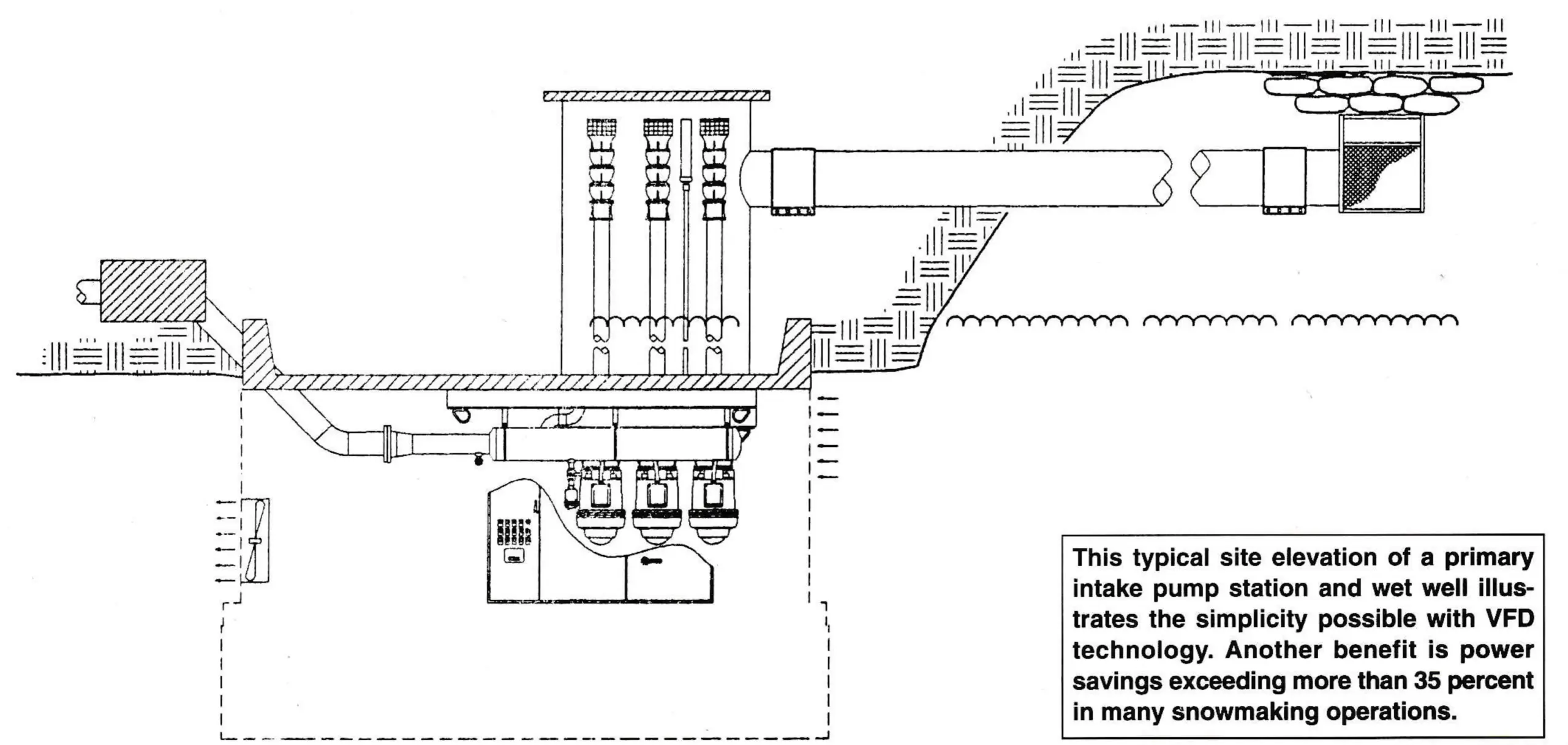
A different approach to pump system control is variable frequency drive (VFD) technology which is well established in industrial America but fairly new to ski areas. VFD systems use standard pumps and AC voltage motors like those found on conventional systems. However, they don’t need valves to bypass or regulate pressure. This is because VFD systems use solid-state electronics, powerful software and computer controls to automatically change pump speeds. Such precision lets them exactly match flow requirements. Best of all, the electronic controls let operators easily change and monitor pump performance.
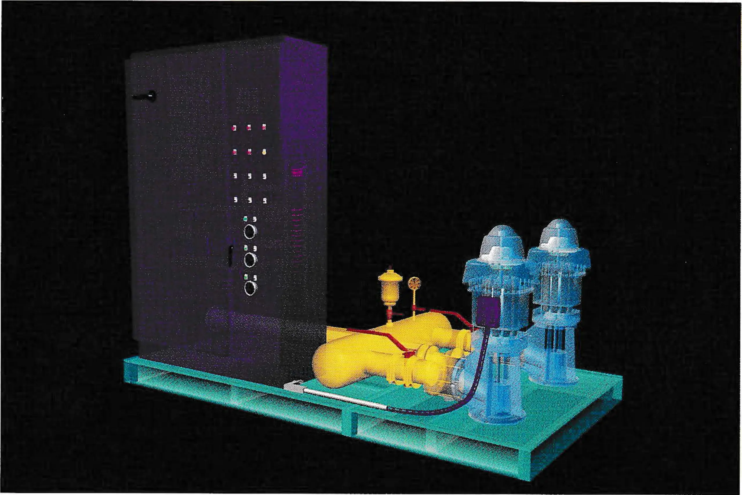
Integrated VFD systems automatically change pump speeds by using a programmable logic controller (PLC), electronic pressure transducer and an alternating current frequency inverter. As demand is sensed, the PLC instructs the VFD-driven pump to change speeds and maintain constant discharge pressure. In this sense, VFD systems are like cars with cruise control. They adjust RPMs to maintain a constant speed or, in this case, a constant discharge pressure.
To keep costs down, only one pump in a VFD system actually has a variable frequency drive. Additional pumps run at fixed speeds and are brought on-line when the PLC senses that the VFD pump can’t maintain discharge pressure by itself.
The net effect is that by using only the exact, required horsepower, motor life and power savings are enhanced. Many pump system operators have documented 35 to 40 percent power savings after replacing conventional pump stations with VFD stations.
An excellent example is Colorado’s Beaver Creek Resort. In 1989, snowmaking manager Bill Kennedy changed from conventional to VFD controls. He also doubled the system from 500 to 1,000 horsepower and increased the volume of water being moved more than 40 percent, to 115 million gallons annually. Despite those huge increases, Kennedy estimates his power consumption increased only 20 percent.
Efficiency aside, VFD systems also offer simplified design requirements, Without control valves, the mechanical layout and pump house can be smaller, reducing construction costs. Eliminating control valves also reduces water turbulence and its associated problems.
Perhaps the biggest concerns about VFD systems are costs and service. VFD systems typically cost more than conventional systems because their solid-state electronics and software are an additional expense. However, the difference is usually paid back within three to four years through power savings and reduced maintenance costs. VFD systems also require properly trained service technicians. But well protected, solid-state electronics are at least as reliable as conventional controls. Also, ski areas with SCR drives on their lifts have technicians who can probably cope with VFD systems.
Pump Glossary
| Term | Definition |
|---|---|
| bowls | Casings surrounding the impeller on a vertical turbine style pump. |
| brake horsepower (BHP) | The horsepower required by a particular pump to operate at a given flow and pressure. |
| check valve | Lets water flow one way only. These should be installed on the discharge of individual pumps on a pump station. |
| control panel | Enclosure containing the pump station’s logic (or brain), plus the motor starters and disconnects. |
| foot valve | A check valve designed to be installed underwater. It holds water in a suction line to avoid priming. |
| horizontal end section centrifugal pump | Single stage pump which horizontally mounts on pump station. Pumps can be either foot mounted with a separate motor, or close coupled with the motor being an integral part of the pump. |
| impeller | Rotating vanes in a centrifugal pump |
| multistage | Multiple impellers included in the same pump. Each impeller adds incremental pressure. |
| programmable logic controller (PLC) | Industrial grade computer uses solid state electronics and powerful software to replace electromagnetic timers and relays. |
| pressure reducing valve (PRV) | Also called control valve or Cla-Val (brand name). Located on the discharge side of a fixed speed pump station, it’s designed to reduce high pressures to the desired pressure in the piping. |
| pressure switch | Opens or closes a circuit when a preset pressure is reached. |
| pressure transducer | Solid-state electrical device which sends an electronic signal proportionate to pressure. |
| pressure relief valve | Pilot operated valve opens when the upstream pressure exceeds the pilot’s setting. Protects irrigation piping from excess pressure. |
| vertical solid shaft motor | Vertical motor with a solid shaft protruding from the bottom of the motor. It’s connected to the pump with an adjustable coupling. |
| vertical turbine pump | Vertical multistage pump consisting of impeller assemblies suspended by a column pipe below water level. |
| variable frequency drive (VFD) | Solid-state electronics which can change the speed of a fixed-speed motor. Eliminates the need for a pressure reducing valve. |
| vertical booster station | A secondary pump station located partially up the mountain to boost pressurized water entering from the primary pump station. |
| vertical wet well station | Pump bowl pulls water directly from wet well or lake. |