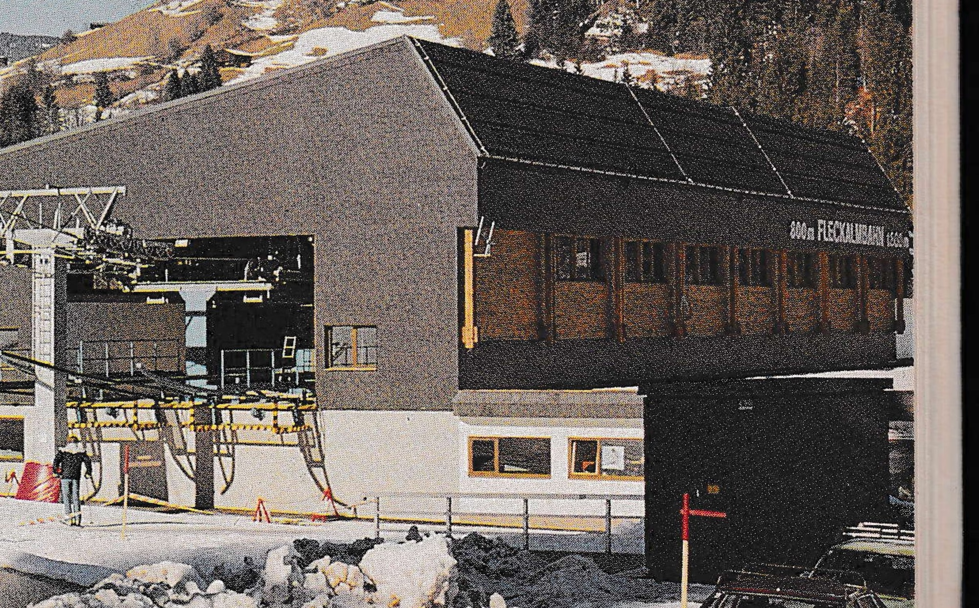


Beyond this lift, which is rated as the largest in the world, Artur Doppelmayr, president of the company, had this to say about what the future holds in lift development:
“In my opinion we will see more and more such big installations in the future. The ski areas will try to avoid intermediate stations since they are very expensive, so the gondolas will get larger. The maximum size is not reached yet, it would be possible to go up to a rope diameter of 55mm. Regarding the HP I think the gondola in Kitzbuehel is the maximum.
“In over two years such big installations will also be built in the U.S.”
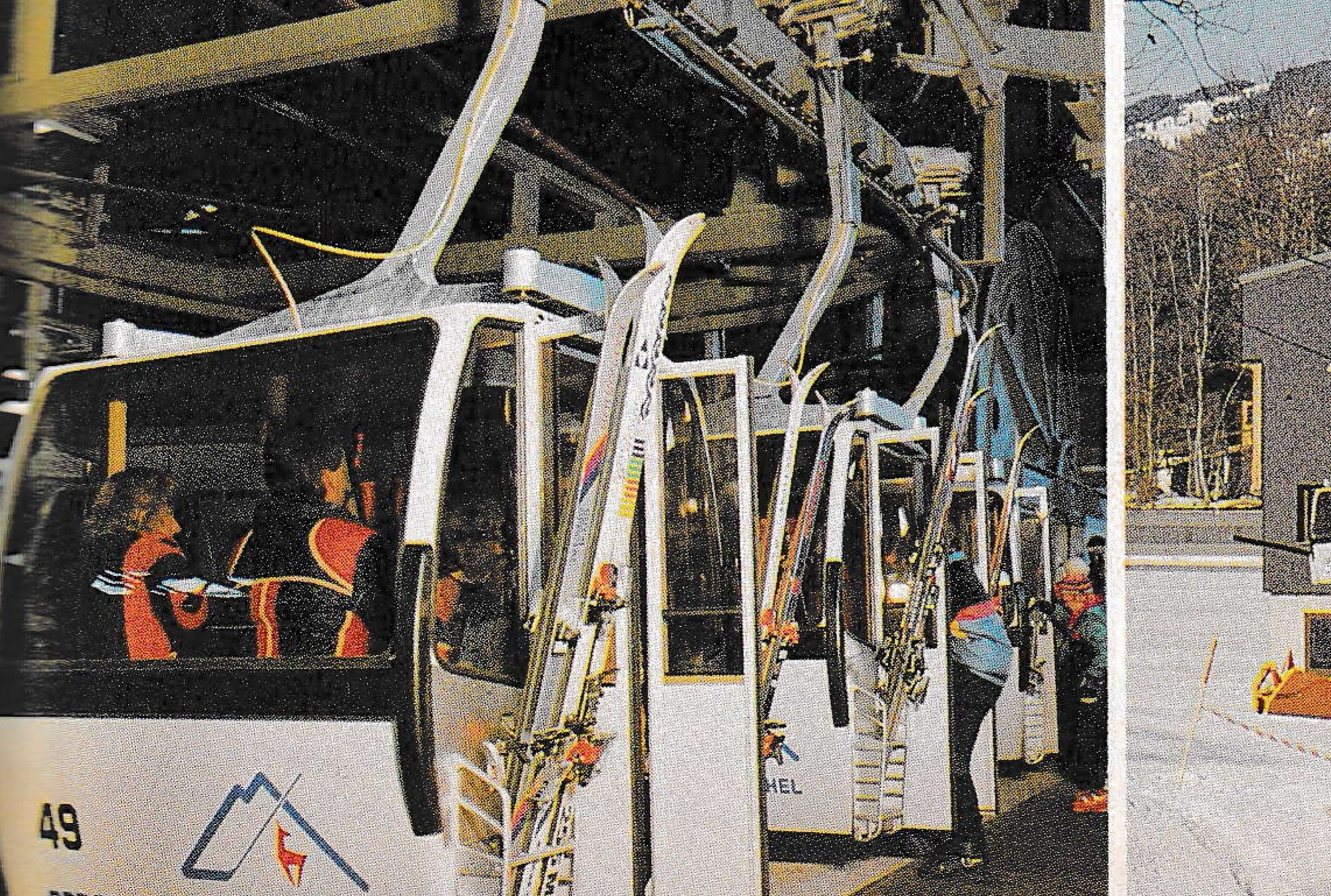
The new Doppelmayr monocable gondola system in Kitzbuehel, Austria has 178 six-seater cabins and is capable of a capacity of 2400 PPH at a line speed of 1000 FPM. With a length of 3983 m (13,068 feet) and the vertical rise of 987 m (3,238 feet) as well as four DC motors, this is the largest lift installation (VTFH) in the world to date.
The drive machinery is located in the top terminal and tensioning in the bottom terminal. The terminal framework is supported by center masts. This framework consists mainly of the grip opening and closing lines, acceleration and deceleration units and a terminal conveyor system. The acceleration and deceleration lines consist of tire conveyors. These air-filled rubber tires are pressed onto the grip top. The tire conveyor extends in front of and beyond the acceleration line to guarantee controlled movement of the cabin. The acceleration and deceleration units are driven directly from the haul rope by the bullwheel, by means of a Duplex chain, angle gearboxes and U-shafts. At the fastest point, the U-shafts drive V-belt pulleys and all tires are linked with a V-belt system. The transmission is rated so that the cabins are synchronized with the rope speed at the grip opening line and then decelerate to a speed of 60 ft./min. (0.3 m/sec.) for the low terminal speed.
The terminal conveyor chain transports the gondolas from the decelerator to the unloading area around the 180 degree turn and through the loading area to the start position. This conveyor chain is also driven by the bullwheel by means of angle gearboxes and U-shafts so that it reaches the required 60 ft./min. (0.3 m/sec.) terminal speed.
The chain drive can be connected or disconnected by a 24-volt magnetic clutch. Before the start position is reached, the terminal conveyor runs the cabin to a short tire conveyor. This tire conveyor prevents a pile-up situation and can park up to four cabins controlled by cabin position switches. The unit is driven by an electrical gear motor.
The door opening rail is located behind the deceleration line and the door closing rail is in front of the acceleration point. A limit switch located before the start position checks the door position. If a door is not closed properly it causes the gondola to stop and the installation is shut down.
The entire terminal area has cabin guide rails and at the loading and unloading area there are floor guides to avoid any swinging of the gondola during loading and unloading.
The terminal machinery is equipped with platforms and hand rails, mainly at the grip opening and closing lines, the acceleration and deceleration units and at the drive unit of the terminal conveyor chain. They are accessible by permanently-installed ladders.
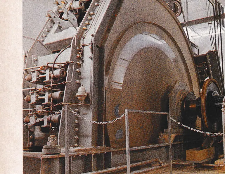
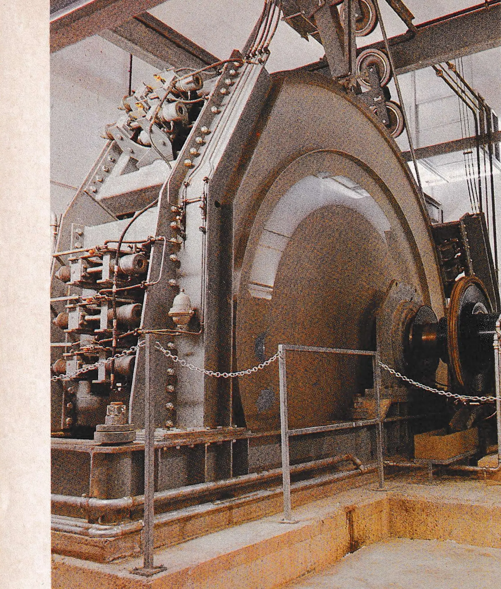
The gondola drive is equipped with a 5.5 (18 foot) diameter vertically installed bullwheel, driven by two gearboxes which are located on either side of the bullwheel. Gearbox #1 is driven by two DC electric motors (#1 & 2), gearbox #2 is driven by motors #3 and #4. Each of the electrical DC motors has an output of 440 KW (600 HP) at 1270 RPM. The armature voltage is 400 volts. Therefore, the total continuous output available is 1760 KW or 2400 HP. This HP output allows the maximum capacity of 2400 PPH at a line speed of 1000 FPM (5.0 m/sec).
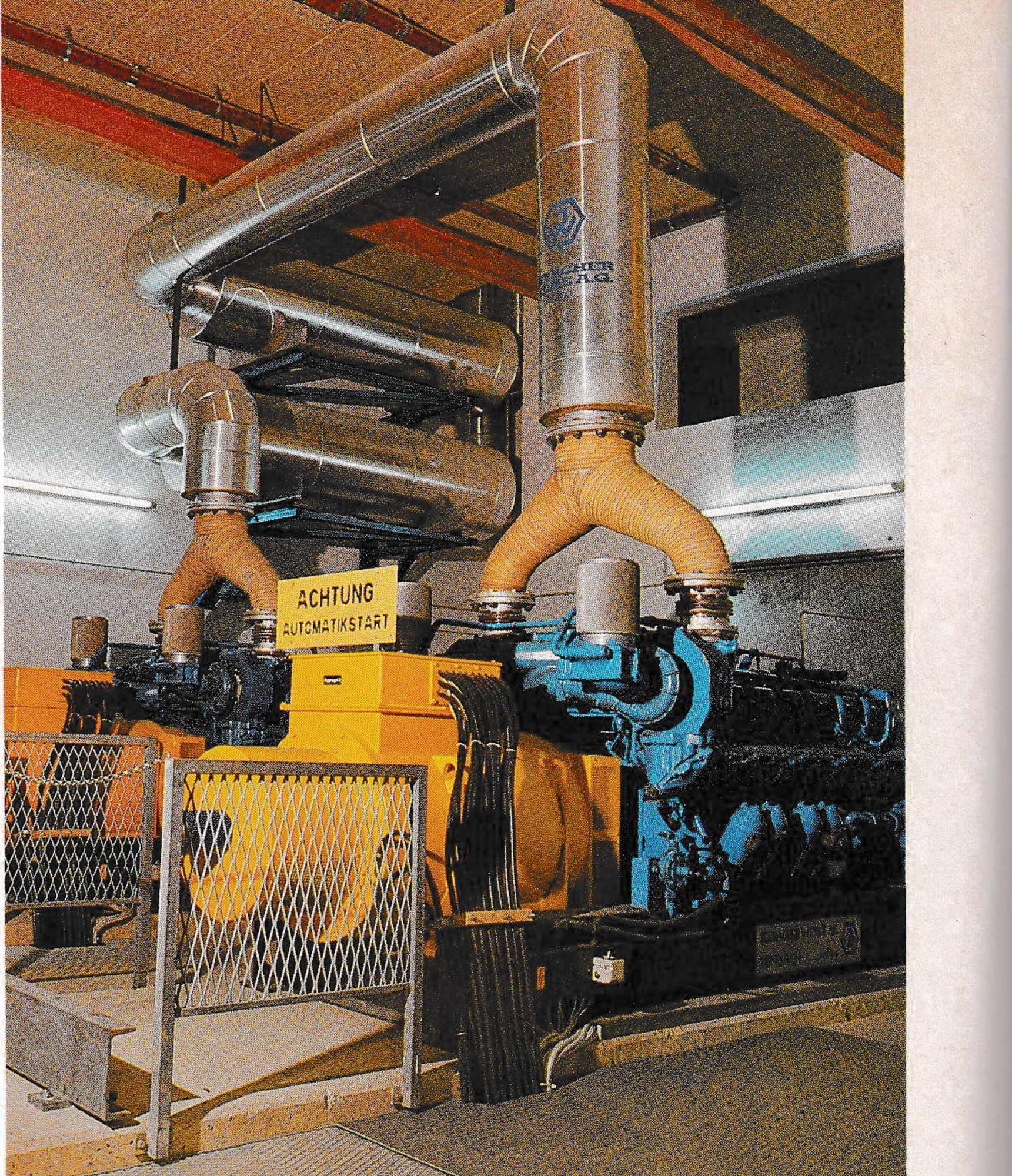
Four different cabin intervals are adjustable to deliver four different capacities. Due to the peculiar power supply situation in Kitzbuehel, an independent power supply with 2 x 1200 KVA was installed (Diesel generators).
In each terminal, the gondolas have controls and monitors of all safety devices and switches in the terminal, such as an anti-collision system.

The two terminals are connected by three communication cables. One cable transmits signals; the second cable is for the tower derailment indication, the loud speakers and for the two wind speed meters; and the third cable serves for voice communication purposes.
Due to the length of this installation, the low voltage control equipment was selected very carefully. An additional programmable automatic device, SIMATIC S5-130W, was installed to control additional operation control and information tasks. These additional information and control tasks include the indication of the cabin position on the line.
The inclined length of the gondola is 3983 m (13,068 feet) and is simulated at a line fault indication schematic with 180 light diodes per rope side. At each stop, the stopping distance and stopping time are indicated. The derailment indication shows the tower number where the derailment occurred.
For the auxiliary drive, one hydrostatic motor was set up per gearbox. The installation can be driven with either gearbox. Both are separately able to take the whole torque for the auxiliary to empty the lift.
Except for tower #1, which is a tapered-box tower, all towers are lattice type and hot-dip galvanized. All towers are bolted onto the foundations, have full length ladders and starting from 18 m (60 feet) in height, they are equipped with intermediate rest platforms. They also have fixed rope lifters and 60 cm (2 feet) wide catwalks along the sheave assemblies.
The support sheaves have a diameter of 500 mm (20 inches), the holddown sheaves are 400 mm (16 inches) diameter. Only boltless sheaves are used. All sheave assemblies have rope catchers, the assembly frames are hot-dip galvanized. The support assemblies are equipped with break-fork switches in the rope catcher and the hold-down assemblies are equipped with break-fork switches actuated by drop-sheaves.
The grips are the Doppelmayr double grips with integrated grip force testing. The grip works over a lever system and the gripping force is achieved by cup springs. The grip is totally non-destructive tested.
All fine casting parts are inspected by an authorized laboratory for notch impact strength, breaking strength, and elongation value, and are searched for casting flaws.
Six-seat cabins made by Swoboda are used with a four-point suspension. The cabin swivel doors are automatically opened and closed. The door mechanism is actuated by a push-pull cable from a roller lever which sits on the cabin hanger and is pushed up or down by the opening or closing rail.
The installation of the gondola necessitated construction of base area structures, a parking lot at the bottom station providing space for 50 buses and more than 500 cars and also improved the infrastructure of the whole area. This new six-passenger gondola contributes toward making one of the most beautiful ski areas in Tyrol more easily accessible.
| Item | Value |
|---|---|
| Name | Fleckalmbahn |
| Location | Kitzbuehel, Tyrol |
| Built in | 1983/84 |
| Built by | Doppelmayr Company |
| Type | 6-passenger monocable gondola |
| Slope length | 3983 m (13,068 ft) |
| Vertical rise | 987 m (3,238 ft) |
| Average grade | 25% |
| Capacity | 2400 PPH |
| Line speed | 5.0 m/sec (1000 fpm) |
| Terminal speed | 0.3 m/sec (60 fpm) |
| Carrier interval | 9 sec. |
| Carrier spacing | 45 m (147.6 ft.) |
| Travel time | 13.32 min. |
| Loading conditions | 100% uphill, 100% downhill |
| Drive terminal | type: under floor drive; location: top terminal (basement); primary: 4 x 600 HP DC electric motors; stand-by: 100% by 2 x 1200 KVA diesel generators; auxiliary: diesel driven hydrostatic drive into gearboxes |
| Return terminal | bottom with direct haul rope tensioning |
| No. of carriers | 178 |
| No. of emergency brakes | 5 |
| No. of service brakes | 5 |
| No. of sheaves | 400 support, 20″ dia. + 64 hold-down 16″ dia. |
| No. of towers | 29 |
| Rope diameter | 50 mm (2″) |
| Spliced rope length | 8166 m (26,791 ft.) |
| Bullwheel diameter | 5.5 m (18 ft) drive, 5.0 m (16.4 ft) return |
| Direction of rotation | CW – left up |