
The accuracy of the original survey of a liftline is extremely important as the profile plotted from the survey forms the basis from which the lift is designed. If an undetected error is made in the survey, the rope deflections, the ground clearances and the tower roller loadings will not coincide with the design, and the lift may be unacceptable or even dangerous.
The number of surveying errors over the years, in fact, has been of enough concern to warrant government action. Several years ago in Canada, for instance, the British Columbia Department of Commercial Transport found an error of nearly 10 feet in elevation on an area chairlift. Alarmed over the potential danger of the lift, they insisted that all future survey methods be self-checking and that a copy of the surveying notes be filed with their office. Furthermore, they required that an “as built” survey be made of each lift to check not only the original survey but the construction surveying as well.
Despite the obvious importance of an accurate lift survey, it has been the experience of the author and other lift consultants that there have been far too many surveys in which errors were made. Reason? The survey methods used were not self-checking. As a guide for the area operator, the following outlines a self-checking method which has proved to be absolutely reliable for the surveying of T-bars and chairlifts.
The survey of most lifts requires that many permanent reference points, used not only for design purposes but for installation of the lift, be established along the liftline. On most lifts these points must be in a straight line in plane and the relative elevations and horizontal distances (chainages) between reference points must be accurately determined.
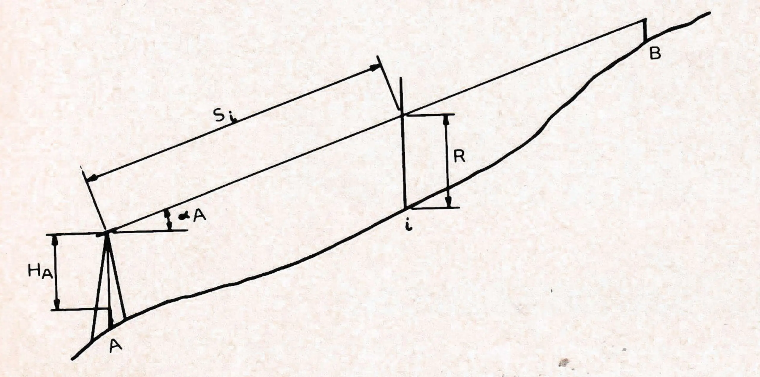
One easy method of assuring that the line is straight is to establish a point on the extended line at “infinity,” such as a tree on the horizon or a high stake placed at the far end of the line. The transit should then be oriented on this point. If the line goes over a hump so that the “infinite” point is invisible, shooting circle left and right and bisecting the distance between the tacks on the next stake will eliminate local errors in carrying the line along until the high stake or “infinite” point is visible again. A method we use for establishing the control points, usually about 100-200 feet apart, is shown in Figure 1. It is self-checking, as two sets of readings are made for each course.
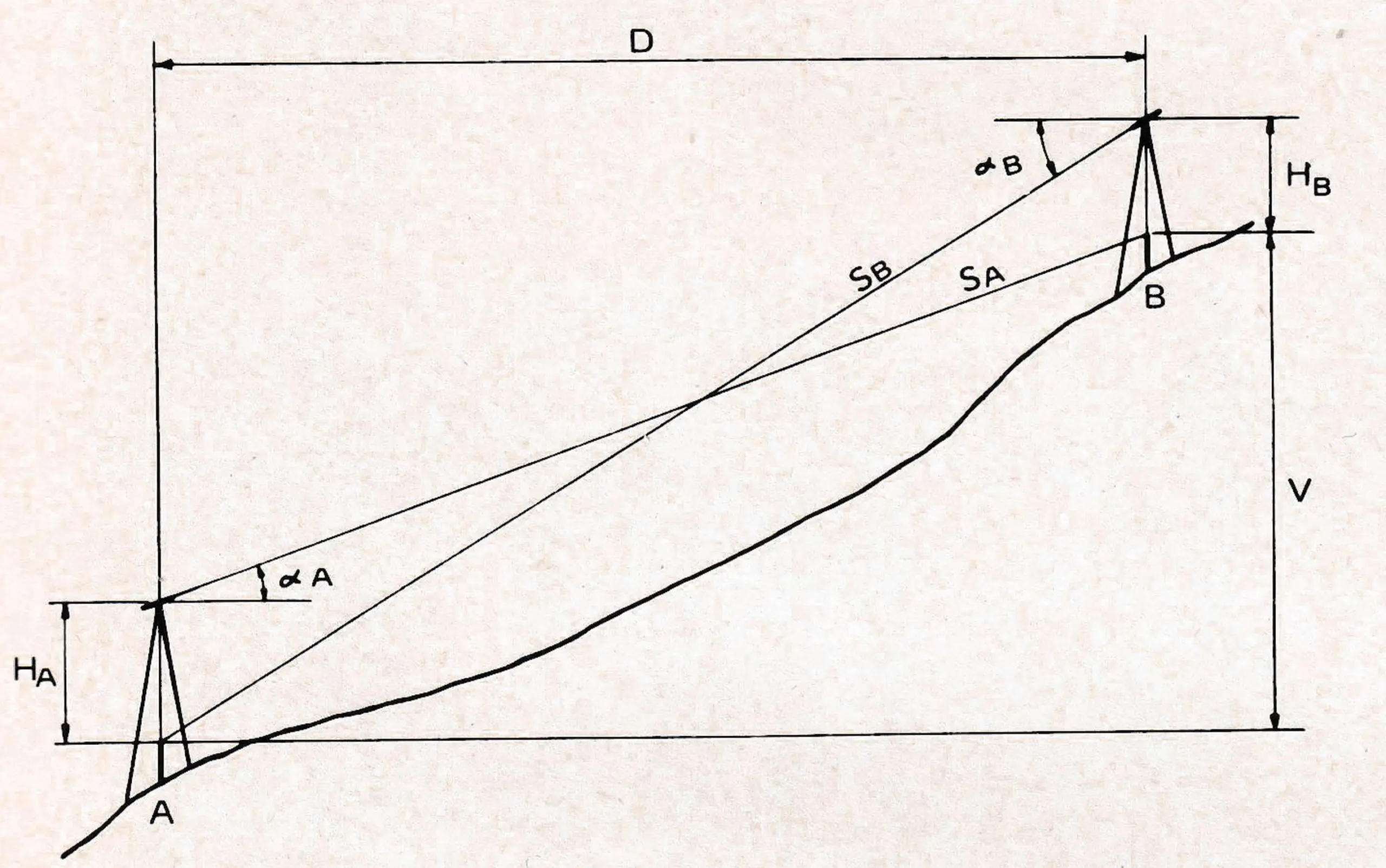
In Figure 1, we set up at A. We measure the height of the instrument HA over the top of stake A, the height of which is also measured and recorded. We then shoot the vertical angle αA to the top of stake B and measure the distance (SA) from the horizontal axis of the instrument to the top of stake B. We then set up at B, measure HB, measure αB to the top of A and chain SB. As αA and αB differ substantially as do SA and SD, two sets of