

The above sentence is quoted from ANSI (American National Standards Institute) B-77.1-1976 Standard, Article 2.3.3.1.2, Page 30, which defines safety requirements for aerial passenger tramways. As the “B-77 Standard” has been adopted by a large number of state authorities, the U.S. Forest Service, and the two major ski lift insurance carriers in the United States. as their governing standard, the stipulated requirements thus need to be adhered to. An almost identical requirement is part of the Canadian equivalent, the CSA (Canadian Standards Association) Z-98 Standard.
Interestingly, although these standards went to great lengths of detail about some aspects of lift or aerial tramway design, certain essential (but possibly controversial) aspects of lift design are passed over in one generalized statement, as is the one quoted here. This statement is in obvious reference to what, is commonly referred to as the “tower derail (or deropement) safety switch.” Thus the standards do not say what type of “suitable device,” where or how it should be mounted, or how it is to sense the “case of deropement.” Those individuals who are intimately involved with the design, operation and maintenance of lifts, are, however, keenly aware that this generalized statement packs a broad scope of interpretations.
To analyze the intent of the Standard in this regard, it is necessary to explore all the ramifications of the problem: (a) how a deropement can be physically detected; (b) how the physical detection of the deropement can be translated to interrupt the safety circuit and stop the lift; (c) how to prevent the system from becoming inoperable due to some abnormal or extraneous unexpected forces; and lastly (c) testing the satisfactory operation of the system. To simplify the analysis, consideration in this text is given in specific reference to fixed grip chairlifts; however considerations for surface lifts, detachable gondolas or detachable chairlifts would generally be similar, with only minor variations.
Reliability of detection in the event of deropement is as important as reliability of continuous operation of the lift. Hence, the conscientious owner/operator wants not only to be satisfied that the system meets the vague intent of the standard to allow him to operate, but needs to be at ease with himself that the deropement safety switch system used on his lift(s) will activate regardless of the type of deropement, i.e. whatever path the rope may take, if and when, and for whatever unexpected reason, it leaves the sheaves.
Immediate stoppage of the lift, upon such condition, is essential to the prevention of substantial damage to the equipment and possible loss of life or cause of severe injuries. Equally important, though, to the reliable — and thus profitable — operation of a chairlift, is that the system be as trouble-free as possible in normal operation, and that it will not become ineffective in the course of time due to the effects of the elements or other causes.
While the initial cost of the safety switch equipment is sometimes a consideration, the long-range costs, incorporating maintenance, annual testing, possibility of down-time, equipment damage and/or casualty, need to be considered in the over-all casualty, need to be considered in the over-all economics of a deropement detection system.
It is only proper, at this point, to acknowldge the cry which may be raised by some who state that safety switches are really only a back-up system, that if the lift is properly designed, with adequate sheave loadings — as prescribed in considerable detail by other paragraphs of the B-77 Standard — safety switches should in reality not be necessary; hence anything that could be interpreted as meeting the intent of the standard, should be adquate. Although there may be some truth to such a claim, the knowledgeable individuals who were entrusted with compiling the standard, obviously felt that a backup is necessary.
A review of the various systems of devices that have been or are in use for the detection of deropement, indicates that they fit into three general design categories, based on assumptions of what may occur, and therefore, how to detect the occurence:
(1) ‘Prescribed Path’ design, the proponents of which theorize that the rope will generally take the path of least resistance, or what can be thought of as a prescribed path — a path identified by those other parts of the standard which define rope derail guards and rope catchers. Adherents to this theory of thought feel that the inside derail guard will (or should, at least) effectively deflect the rope, or otherwise prevent the rope from falling to the inside, and that in case of a deropement to the outside, the rope will fall onto the rope catchers. Thus they feel that no device is needed to detect a possible inside deropement (rope will be deflected back; i.e. an inside deropement “cannot” happen); and that for the outside deropement event, the rope will fall onto the rope catcher, hence the “suitable device” must be of some type that will become activated just before the rope comes to rest on the rope catcher.
Devices which are designed to sense deropement under these conditions include mechanically-actuated, wand-type, snap contactors, and fracture-type switches. The fracture-type switches are notched conductors such as a brittle wire, bar or printed circuit board.
This design theory rules out the possibility that the rope could follow other paths in the event of a deropement, such as inside deropements where the rope jumps entirely over the inside deflector, or becomes jammed between the deflector and the sheaves, or in case of outboard deropements, where the rope falls completely outside the rope catcher.
(2) ‘Sheave assembly reaction’ design, a theory which asserts that situations may arise wherein the rope may not follow the assumed path, with the lift thus failing to stop. It recognizes that the resulting damage could be substantial. This design therefore equips each sheave assembly with an unbalancing device (spring or weight) which, in the event of deropement from the sheave assembly, causes the sheave assembly to assume an abnormal position (tilt), and thus positively activate a device to stop the lift.
The weight-actuated systems use a weighted sheave on the incoming sheave assembly pair, with the tilting motion of the sheave assembly then being used to fracture a notched conductor, or dislodge a spring-actuated snap conductor, or dislodge a spring-actuated snap contactor. The notched conductor may be a brittle wire, bar, or printed circuit board. The spring-actuated systems use a spring-loaded mechanical linkage between the sheave assembly and the tower arm to activate either a knife switch or a guillotine switch, which cuts a wire between two terminals.
(3) ‘Rope position sensing’ design.
The proponents of this design are basically opposed to expecting that the rope would, in a deropement situation, follow either a prescribed path or allow the sheave assembly to assume any predetermined reaction position. The proponents of this design generally agree that the sheave assembly reaction design is a step in the right direction, but are concerned that unforeseeable circumstances, or other simultaneous conditions could occur which could preclude the sheave assembly from reacting according to design, thus preventing the activation of the deropement sensing device. They believe, for instance, that a partial inboard deropement which jams the rope between the inside deflector and the sheaves could prevent the assembly from tilting; or that excessive friction in the pivots or icing or other extraneous conditions could prevent the sheave units from reacting in the event of a partial or complete outside deropement.
Therefore, the rope position sensing design is based essentially on the continuous monitoring of the rope in its normal position, so that any departure from the rope’s normal running position activates the sensing device.
One type of deropement detection device of this design is the so called ‘trailing arm’ mechanical sensor.
This device is a roller mounted on an activating arm, which in turn is mounted on the sheave assembly. The roller is spring-loaded or weight-loaded against the rope on the incoming side of the sheave assembly. Deropement by the rope in any direction from its normal running position is designed to derail the trailing arm roller, causing it to activate the switch mechanism. Circuit interruption is caused by snap contactors actuated by the roller arm.
In the United States, a more commonly used deropement detection device of this type is the proximity (or magnetic balance) type switch. The operating principle of the proximity type switch is based on the alternate making or upsetting of a balanced magnetic field in which the contact mechanism is placed.
The magnetic balance proximity switches have no external moving parts subject to wear and servicing.
They continuously “look” magnetically at the rope in its normal position. They signal if the rope isn’t where it should be, thus providing exactly the information that is expected of this device, providing of course that the design and construction offer the required degree of reliability.
Thus far we have looked at various systems by which deropements are intended to be detected, and have indicated the switch types that are commonly used in America. Since varying systems of deropement detection use, in some instances, similar or identical circuit interruption devices, we will examine these in groups and then explore problems that could arise, and solutions.
Section 2.1.9.5 of the B-77 Standard requires that “electric stop control circuits shall be energized circuits so that, in the event of electric power failure, the system will fail-safe and the tramway shall be inoperative”. Thus switches must be of the so-called ‘normally open’ type. This means that the contacts will be closed when the lift circuit is energized, and the lift is in a safe operating or ready-to-operate condition. A deropement at any sheave assembly would then cause the switch contacts to open, interrupt the safety circuit, and stop the lift.

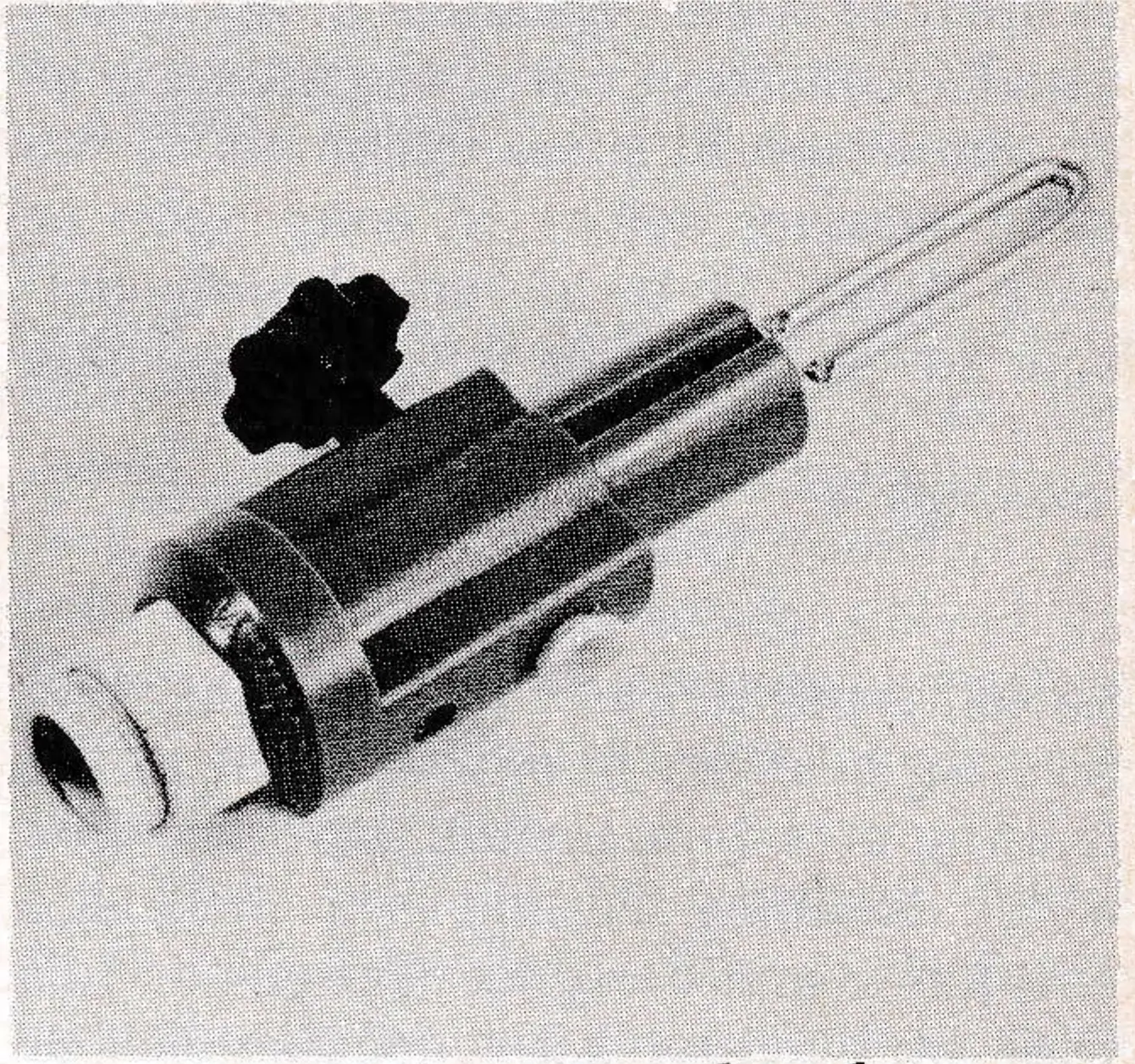
Two general types of circuit interruption systems are in use: fracture and contactor. Fracture-type switches are really continuous circuits that are mechanically severed by the deropement. They usually consist of a heavy gauge, but brittle wire loop, or printed circuit board, notched so as to induce fracture when struck by an external object such as the rope or sheave assembly. The advantages of this system are that it allows for relatively rugged construction at low cost and provides good circuit contact reliability; the disadvantage is that the fractured switch, after actuation, must be physically replaced. Testing of the switch likewise requires physical removal and remounting.
For the Skimmer — A Digest
Below are some of the key points developed in technical detail in the full text
- Tower derail switches are specified in the US ANSI (American National Standards Institute) B-77.1-1976 standards as well as the Canadian equivalent CSA (Canadian Standards Assoc.) Z-98 standard. Although both standards allude to a Tower method and choice of switch is left up to the manufacturer or user.
- Reliability of the switch and the stystem is essential; failure of the system to detect a equipment which will soon mask out the original cost of the system.
- The selection of the the designer or purchaser.
- Some people erroneously feel that derail switches are not necessary if the lift is properly designed.
- Derail switches can be placed in three catagories: 1) Switches which require the rope itself to actuate the the switch; 2) Switches that require the rope to be absent from the sheave assembly; and 3) Switches which require the rope to be in a prescribed area. The absence of the rope in that area actuates the switch.
- Switches must be of a fail safe or continuous loop circuit design.
- The actual switching mechanism can be classed into two types: 1) Fracture type switch; and 2) Contactor type. Within the contactor types there are still two more sub-classifications: a) those which use a mechanically actuating device; and b) those that are magnetically actuated.
- Although fracture switches offer contact reliability, proximity switches theoretically offer the best deropement detection reliability.
- Proximity switches in the past, because of misapplication, have been unreliable.
- The magnetic sensing of the iron in the wire rope is what makes the proximity switch work.
- Ski lift safety circuits are particularly susceptible to lightning caused current surges which will weld the contacts of proximity switches and render them useless.
- All proximity switches must be surge protected at every tower.
- The B-77 standard requires all switches to be tested annually.
Contactor switch types rely on one or two sets of point contacts which may be mechanically or magnetically actuated to open or close. Mechanical actuators usually consist of cams or plungers, or combinations of such, which cause the point contact set(s) to snap open or snap closed. To be activated, some outside force must act upon it. In some switch types this is caused by the rope striking a lever; in others, such as the trailing arm type switch, by the action of the derailing trailing arm. Magnetic actuators are designed either for use with snap-acting point contractors, or reed-type contactors.

Thus far we have noted that while fracture type switches offer rugged construction, low cost and good contact reliability, they are difficult to test, and can only be used in conjunction with detection systems which rely, to some extent, on the rope or sheave assembly performing in an assumed pre-determined manner; hence, one could fail to stop the lift in certain deropement situations.
We have also noted that while the proximity type rope position sensing switch theoretically offers the most reliable deropement detection, it has been known that magnetic proximity type switches have not always offered the necessary operating reliability.
What are the causes of these problems, and are there solutions? The basic cause of the problems stems from mis-application of standard mass-produced industrial type proximity switches to the much more demanding environment which confronts a chairlift deropement switch.
These problems stem from four specific circumstances which affect chairlift switches: sensitivity range, vibration, contact corrosion and current surge. To understand these problems as they affect in particular the magnetic proximity type switches, and to explore what is necessary to overcome them, it is necessary to understand the principle of their operation, and to explore the functioning of those switches now in use.
| Deropement Detection System | Circuit Interruption System | Switch Type | Manufacturer |
|---|---|---|---|
| Prescribed Path Theory | Point Contact | Mech Wand | Hall |
| Fracture Type | Brittle Bar | Borvig | |
| Fracture Type | Printed Circuit Board | Lift Engineering | |
| Sleeve Assembly Reaction | Fracture Type | Spring Activated Guillotine | Riblet |
| Fracture Type | Weight Activated Brittle Wire Loop | Doppelmayr Stadeli | |
| Point Contact | Weight Activated Spring Action | Stadeli (Alteriate) Mueller | |
| Rope Position Senstive Reed | Point Contact | Mech Trailing Arm | Spaa. |
| Point Contact | Proximity | “GO” | |
| Contact | Proximity | Micro used by Ski Lift Intl. and others | |
| Reed Contact | Proximity | Enduratek |
| Micro | GO | Enduratek | |
|---|---|---|---|
| Magnet Type | Alnico | Alnico | Rare Earth Cobalt |
| Sensitivity Range | ½” | ¾” | 1½” – 2” |
| Contact Type | Reed | Snap Acting | Reed |
The operating principle of a magnetic proximity type switch is in the physical phenomenon that like poles of a magnet tend to repel each other. Thus, by using two magnets with like poles oriented alongside each other, a zone of balanced magnetic field is created; this magnetic field is easily upset by a ferrous substance placed within that field. By placing a sensitive ferrous switch within the balanced field so that the contacts are open when the field is balanced, the contact will close when the field becomes upset or unbalanced by the presence of an extraneous ferrous body. For these proximity switches the chairlift rope is the ferrous body: when the rope is in its normal position the contacts are closed, the chairlift safety circuit is continuous, the lift is safe to operate. When the rope departs from its normal position due to deropement from the sheave assembly, the balanced magnetic field is restored, the contacts open, the chairlift safety circuit is interrupted, the lift stops.
Table 2 indicates the principal features of the three magnetic proximity switches in current use in America. The two industrial type switches, “Micro” and “Go” use standard industrial alnico magnets; the Enduratek unit, designed specifically for chairlift use, is equipped with rare earth/cobalt type magnets, the strongest magnetic substance known to man, but decidedly more costly. The result of using stronger magnets is partially indicated by the increased sensitivity range, which prevents normal sheave assembly vibration or rope whip from causing momentary tripping of the circuit. It is also known that continuous vibration causes reduction in the force of magnets; hence the importance of strong magnets in this service for long term reliability.
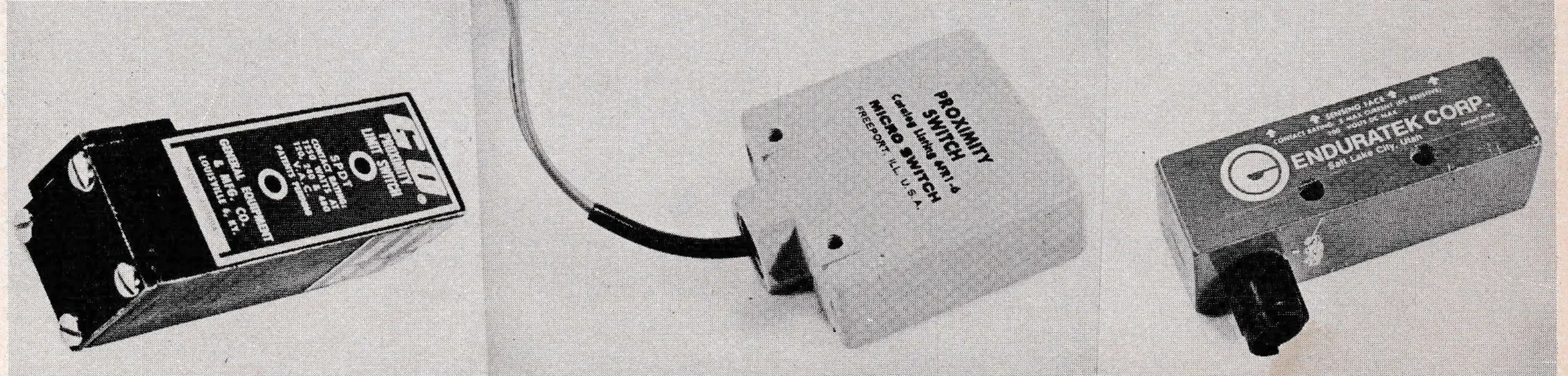
As for contacts, the “Go” switch uses a snap acting armature mounted contact assembly, while the “Micro” and “Enduratek” units use reed contacts in a glass-encapsulated, hermetically-sealed, gas-filled unvironment. This is as critical for magnetic operated switches as for snap-acting witches, as impurities or moisture in the contact chamber can cause contact corrosion which will in time inhibit good contact, and hence could provide erroneous open circuit indication.
Electric current surge, caused by lightning, is a most frequent cause of failure of point or reed contact switches of all kinds. The higher current, or surge, causes contact welding, hence preventing then contacts to open upon malfunction. This has perhaps been one of the severest disappointments in proximity switch (and other point contact switch) usage, as the intended safety that this type switch is to provide then becomes ineffective without any outside indication or warning.
As contact welding has been experienced where no direct lightning strikes have been noted, it was for sometime considered a mystery why industrial-type switch contacts would experience contact welding on ski-lift applications, when none occurred in much longer service in industrial applications. The cause for this is now recognized however, as being due to the so-called ‘antenna effect’. This is caused by the fact that the lift safety circuit in its normal condition is a continuous circuit, and thus becomes, in effect, an antenna of the length of the lift. Depending on terrain, atmospheric, and soil conditions, current surges from lightning strikes within a radius of up to several miles can thus be picked up by the lift safety circuit, and welding of the contacts can result.
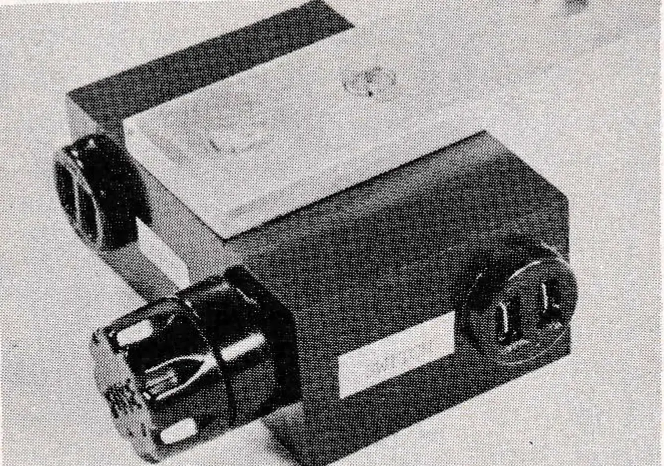
The prevention of contact welding due to lightning strikes or due to current surges caused by nearby strikes, can only be accomplished by use of a suppression device and fuse. Any point or reed contact type safety circuit can and should incorporate one set of such devices for each pair of tower switches, thus effectively protecting each switch from current surge damage.
As a chain is only as strong as its weakest link, so the value of the safety circuit is only as good as its every switch and component. Since normally the system should not open, it becomes of utmost importance that each switch mechanism be tested at least once a year. This is, in fact a requirement stipulated by the B-77 Standard, Section 3.4.1. To test snap type switches of the mechanical type, it is necessary to trip (and reset) each switch manually, a task which can be performed by travelling around the lift on a work chair and stopping briefly at each tower, The same procedure applies to fracture switches, except that each must actually be disconnected and reconnected—a somewhat more time-consuming procedure.
Magnetic proximity switches have presented a special problem: their sealed construction does not make it possible to physically manipulate the contacts to obtain contact opening. Hence, to reliably check each switch, it was necessary that each switch be physically dismounted and remounted—a lengthy procedure. It has then been found that by external application of a strong magnet, most proximity switches could be made to trip; however this procedure is considered potentially risky as permanent damage to the sensitivity of the switch could result by this application of a strong external magnetic force.
To solve the testing problem of its proximity switches, and prevent the potential danger of damage, Enduratek has developed a special switch testing sleeve device. This testing sleeve is fitted with several small but specially calibrated strength magnets, mounted in such a configuration that as the test sleeve passes over a switch, the magnetic balance of the switch is momentarily restored, causing the contacts to open momentarily. The testing sleeve is bolted to the rope of a lift on which these switches are to be tested; as the lift is started, switches on each tower are actuated and reset as the sleeve moves around the lift. It is not recommended that this device be used on other types of magnetic proximity switches as permanent damage or loss of sensitivity could result.
Philip Berger is Vice President and Chief Engineer of Enduratek Corp.