


*Electricity is a form of energy that is used by millions of people every hour to operate homes, offices, factories, schools, stores and practically every other entity of modern life. Electricity is also one of the most essential factors in making ski resorts operate. When it stops, skiing stops and the resort is shut down.*
*Unfortunately, electrical energy is one of the least understood power products. At ski resorts, for instance, electricity powers lifts and, as most supervisors and lift engineers will attest, a high percentage of lift down-time is related to electrical mishaps and misunderstandings.*
*It is because of these failures and other problems related to electricity, that the following article is being presented. It addresses the fundamentals of electricity in basic terms with clear explanations.*
*It is hoped, through better understanding of the many laws of electricity, that ski area personnel might realize better ways to manage this complex form of energy. — Ed.*
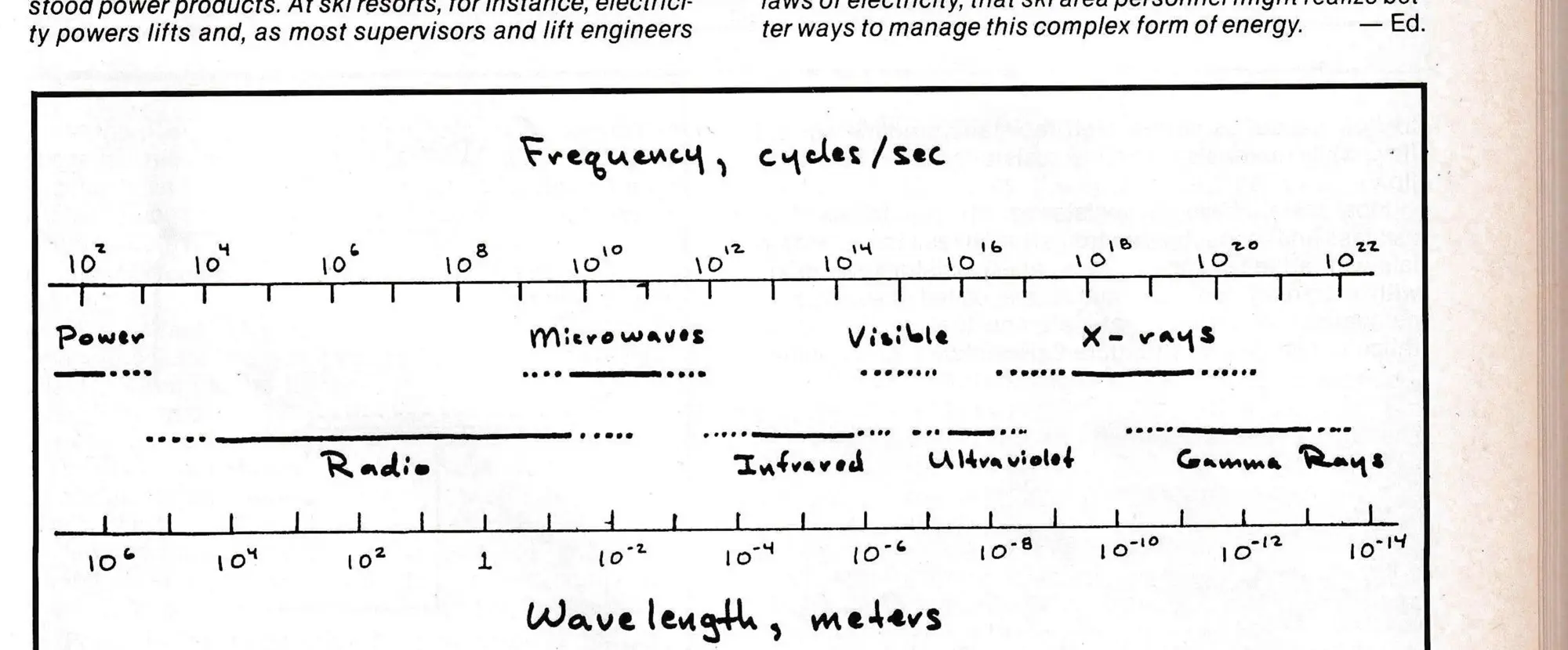
Electrical energy occurs in many forms, ranging from X-rays to laser light, and the various forms of electrical energy comprise the electro-magnetic spectrum (see Figure 1). This spectrum is large and its complexity is well beyond the scope of this article, but the form of electrical energy delivered to ski areas comprises a very small portion of the electro-magnetic spectrum.
To begin any study of electrical energy, it is important to define common terms:
Current is often equated to water flow in a pipe. While this is a good analogy, to be technically accurate, current is better defined as the movement of electrons. Electrons are invisible, charged particles that exist at the smallest level known to man — the intricate structure of atomic matter.
The movement of electrons constitutes a transfer of electrical energy from one point to another and is responsible for “current flow.” Thus, current flow is related to the transfer of electrical energy from one point to another. Current is measured in units of Amperes (A).
Voltage is often equated to the pressure within a water pipe. This is another good analogy, but to be technically accurate, it is better to define voltage as the difference in potential energy levels between any two points.
Electrons will move from one point to another whenever a difference in potential energy exists between the two points. The entire earth has been defined to be at a level known as “ground or zero potential.” Whenever another point exists at a different level, the possibility for energy flow (current) has been established.
Current will always flow from points of higher potential to points of lower potential (like water). The greater the difference in potential (pressure) between two points (voltage), the greater the chance for current to flow between the two points. Voltage is measured in units of Volts (V).
Conductance is the ability of a material to allow current to flow. Materials with a high conductance allow current to flow easily, while materials with a low conductance do not allow current to flow easily.
Most metals have high conductances, while materials such as carbon and silicon have lower conductances. Materials with a high conductance are called conductors, while materials with lower conductance are called semiconductors. A comparison of various materials and their relative conductances is shown in Figure 2. The conductance of a material is measured in units of mhos (℧).
Resistance is the inability of a material to allow current to flow. Materials with a high resistance reduce current flow, while materials with a low resistance allow current to flow.
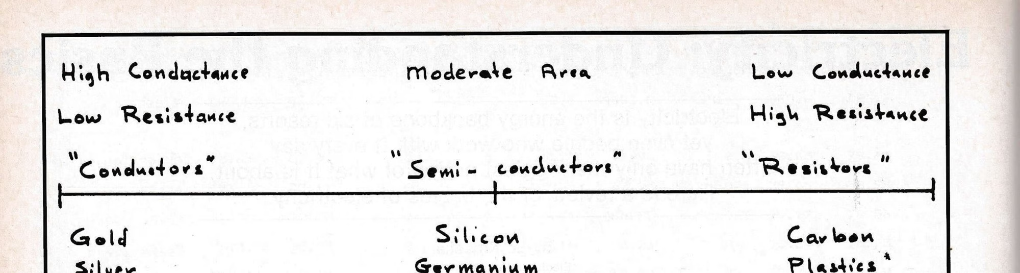
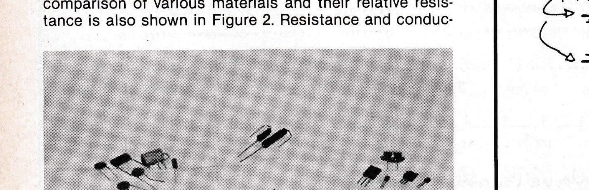
Most metals have low resistance, while materials such as glass and rubber have extremely high resistance. Materials with a high resistance are called resistors. Materials with extremely high resistance are called insulators. A comparison of various materials and their relative resistance is also shown in Figure 2. Resistance and conductance are opposite properties. The resistance of a material is measured in units of Ohms (Ω). Resistors are available in several types, including carbon, ceramic, film and wire wound. Examples of resistors are shown in Photograph 1.
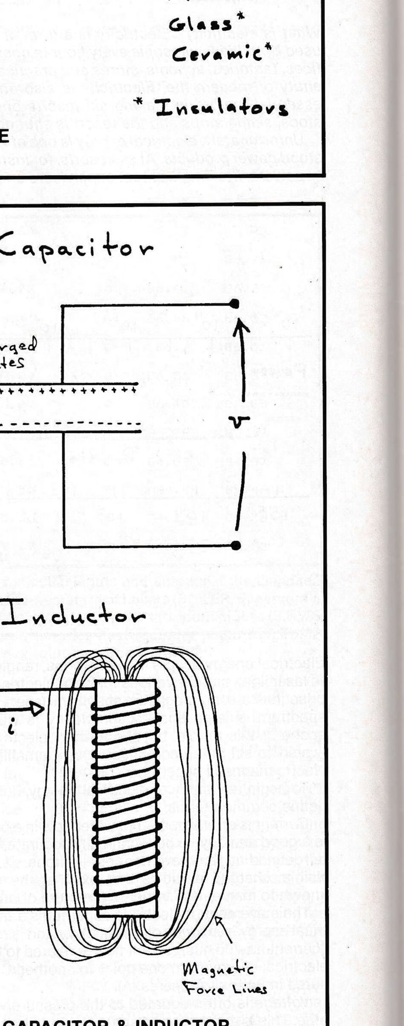
Capacitance exists whenever there is a voltage difference between two points, creating an electric field. A capacitor is a device that is capable of storing the energy associated with an electric field. The capacitor stores energy in the electric field established between its two oppositely-charged plates (see Figure 3). Capacitors are manufactured in several styles, including paper and foil, mica, ceramic and electrolytic. Capacitance is measured in units of Farads (F).
In the past, capacitors were usually called condensers because they stored or “condensed” energy and the capacitor associated with ignition points is still commonly called a condenser. Examples of capacitors are shown in Photograph 1.
Inductance occurs whenever current flows in a conductor, and a magnetic field is created. An inductor is a device that is capable of storing the energy associated with a magnetic field. The inductor stores energy in the magnetic field created around the coiled wires forming the device (see Figure 3).
Inductors are manufactured by winding insulated wire around a core. The core can be a hollow tube, “air core,” or a metallic core, “iron core.” Inductance is measured in units of Henrys (H).
Inductors are often called coils or “chokes” and are commonly used in the tuning circuits of television and radio sets. Examples of inductors are shown in Photograph 1.
Power is the amount of energy consumed per unit of time and is measured in watts (W), kilo (1,000) watts (KW) or mega (1,000,000) watts (MW). The total amount of energy consumed by a device is determined by multiplying the power requirements of the device by the amount of time that the device is operated:
Total Energy = Power Required x Time Operated. Total Energy is usually measured in units of kilowatt-hours (KW-hrs). Electric utility companies bill consumers for the number of KW-hrs used each month.
For the reasons stated above, it is easy to see that power is really an instantaneous measure of the amount of energy a device will consume. Therefore, electric utility companies should be called “energy” not “power” companies. Energy is being produced and consumed, not power.
Direct Current (DC)
Direct Current (DC) is produced by two terminal sources. One terminal is defined to be positive (+) and the other terminal is defined to be negative (—). The assignment or “polarity” of the terminals is fixed and never changes with time. Direct Current is produced by batteries (all types), generators, rectifiers and solar cells. The symbol for a DC source is shown in Figure 4.
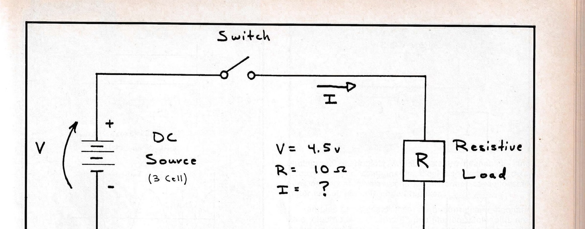
If a resistor is connected to the DC source, as shown in Figure 4, a simple “circuit” is created. If a resistor is placed across the terminals of the DC source, a limited amount of current will flow between the (+) and (—) terminals.
To design, build and maintain electric circuits, it is necessary to know the operational voltages and currents within the circuit. In the simple circuit of Figure 4, the voltage produced by the source and the value of the resistor is known, but the amount of current that will flow between the (+) and (—) terminals is not known. Ohm’s Law is a formula used to determine this:
Voltage = Current × Resistance, or V = I × R
Ohm’s Law can be rearranged to determine any unknown quantity when the other two are known:
- V = I × R — to find voltage when current and resistance are known.
- I = V ÷ R — to find current when voltage and resistance are known.
- R = V ÷ I — to find resistance when voltage and current are known.
One note of caution regarding Ohm’s Law: the formula can only be applied to DC and resistive AC circuits. Ohm’s Law must be modified before being applied to capacitive or inductive AC circuits.
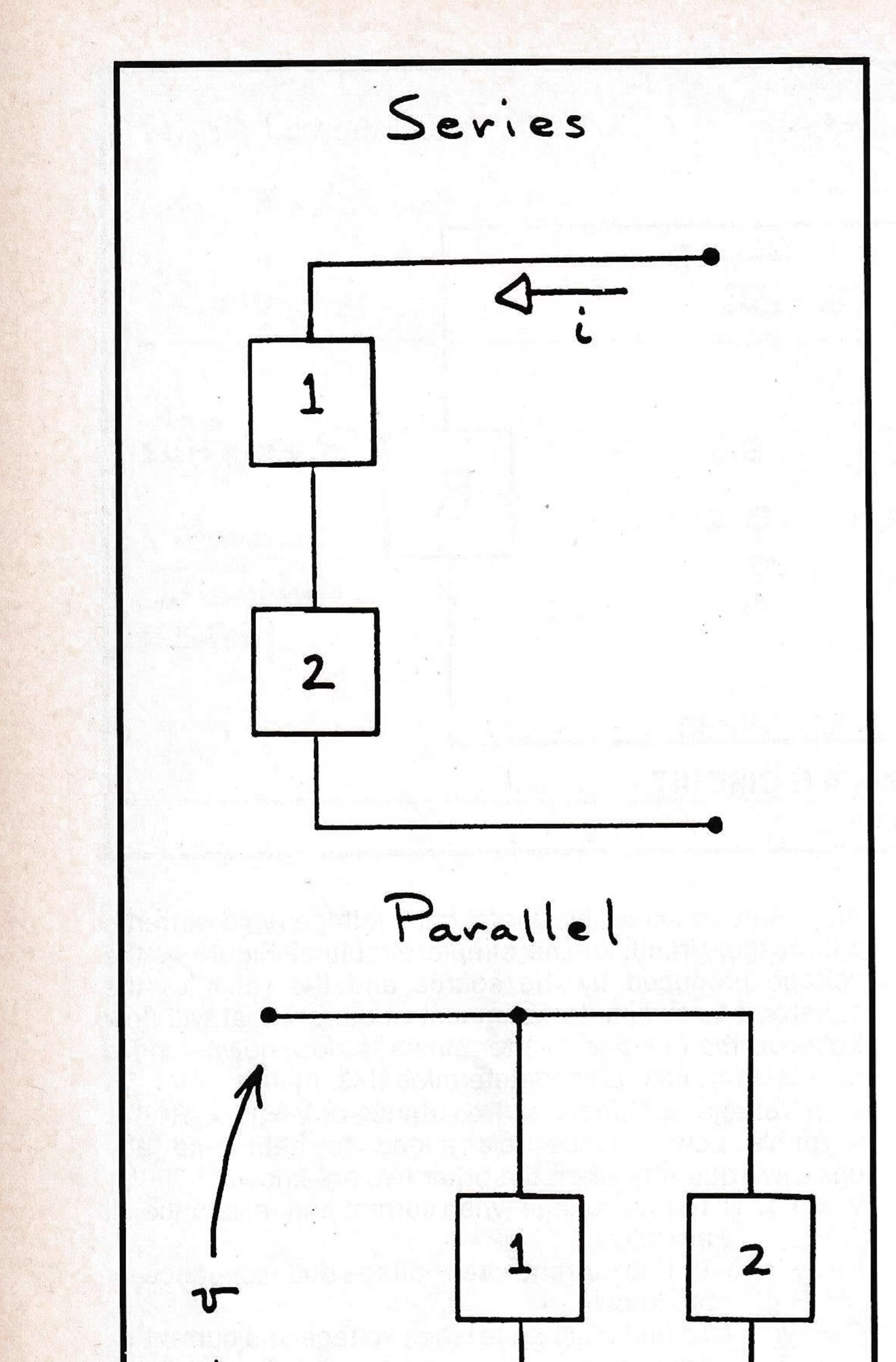
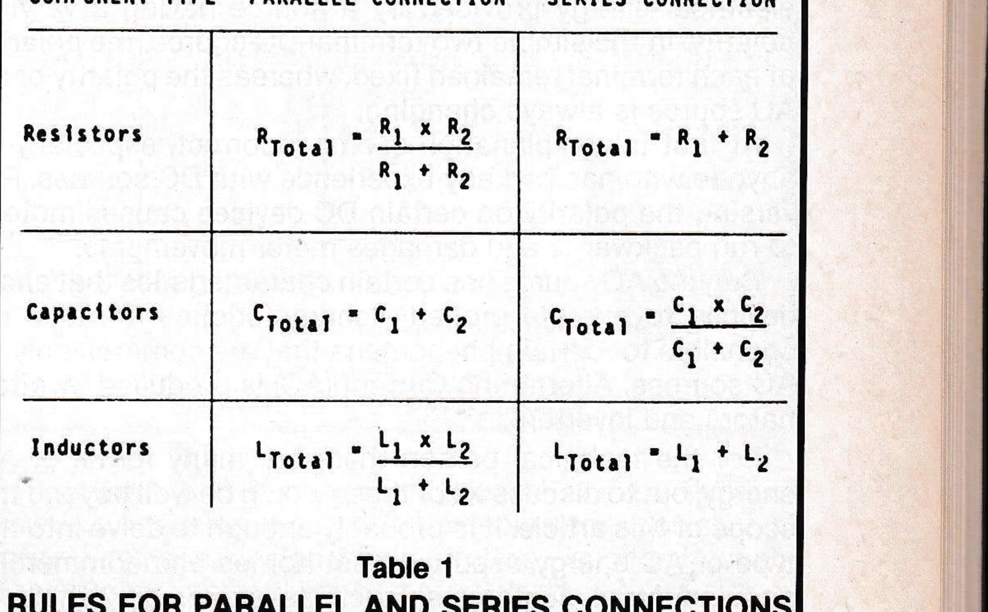
The concept of parallel and series connections is extremely important to the study of basic circuits. Parallel connections are made to allow the same voltage to be applied to each element. Series connections are made so that the same current flows through each element. Examples of parallel and series connections, and the rules that apply to each are shown in Figure 5 and Table 1.
Alternating Current (AC)
Alternating Current (AC) in layman’s terms is a form of electrical energy provided by a source having a varying polarity. In the simple two-terminal DC source, the polarity of each terminal remained fixed, whereas the polarity of an AC source is always changing.
At first this explanation seems incorrect, especially to anyone who has had any experience with DC sources. Reversing the polarity on certain DC devices causes motors to run backwards and damages meter movements.
But, the AC source has certain characteristics that allow devices to operate properly; characteristics are also responsible for certain phenomena that are common only to AC sources. Alternating Current (AC) is produced by alternators and inverters.
For the technical person there are many forms of AC energy, but to discuss all of these would be well beyond the scope of this article. It is probably enough to delve into the type of AC energy used by most homes and commercial and industrial customers, such as ski areas, which is described by this equation:
A cos (ωt)
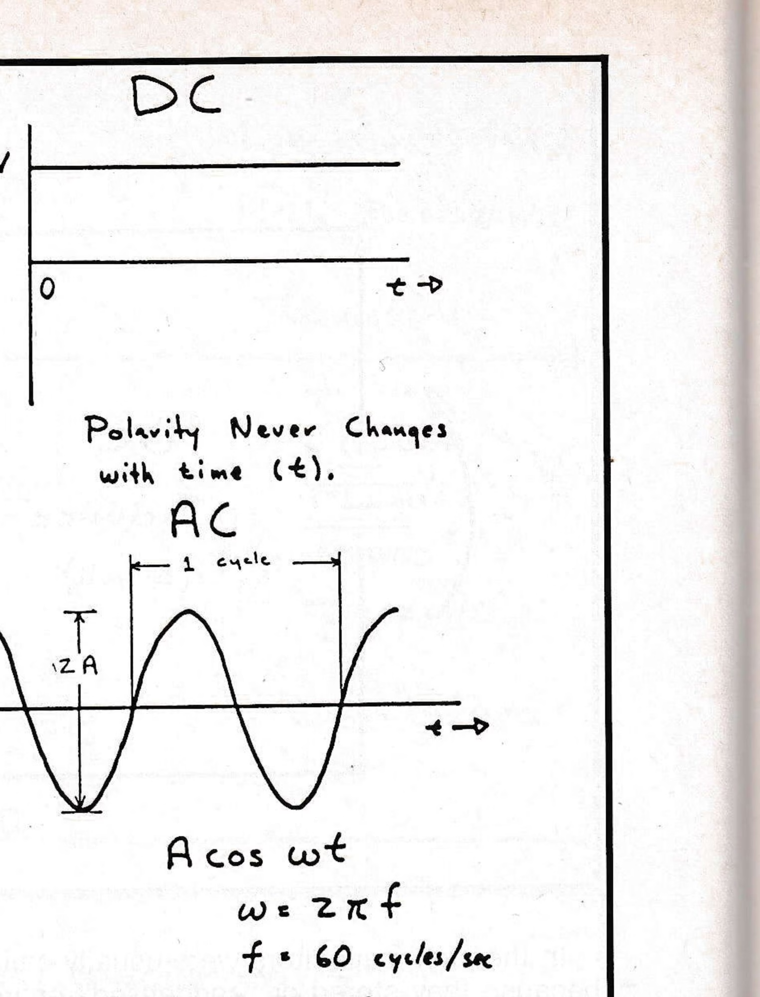
This describes the sinusoidal (alternating) waveform shown in Figure 6. While it seems complicated, a thorough understanding of this equation is not necessary to grasp the principle of AC energy. One important concept that is necessary to understand AC energy is Root Mean Square (RMS) voltages. RMS voltages are only applicable to AC sources and provide a relationship to the effective DC source required to produce the same results in a circuit. A brief description of RMS voltages is provided in Figure 7.
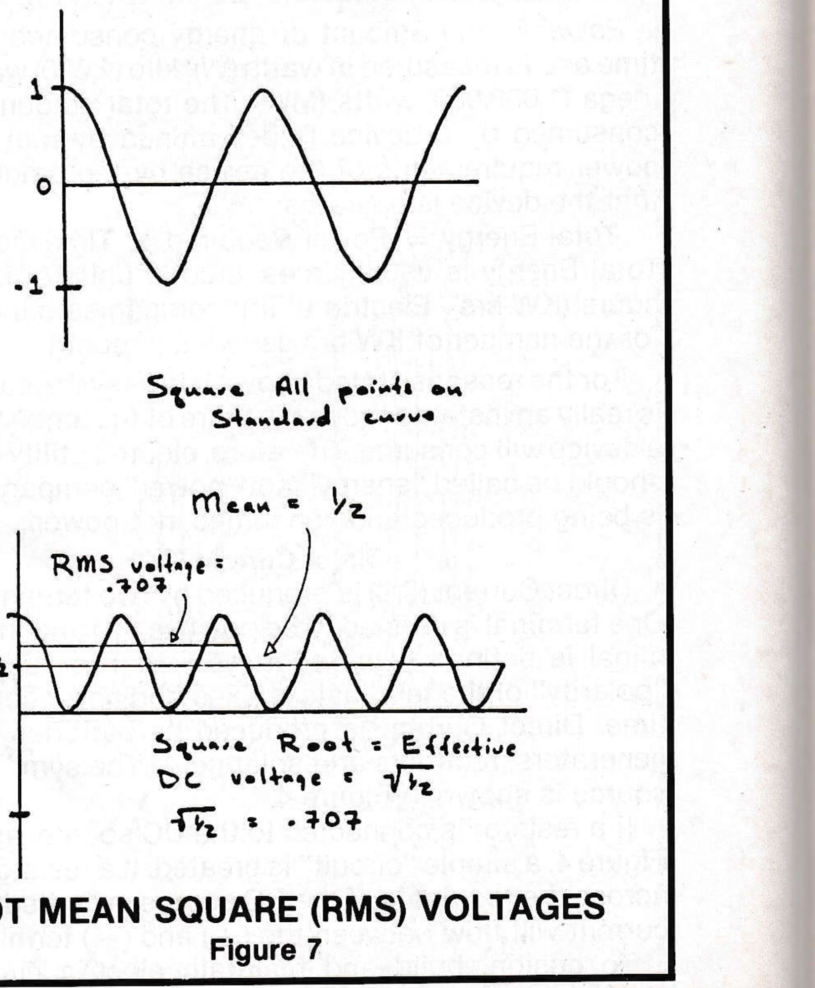
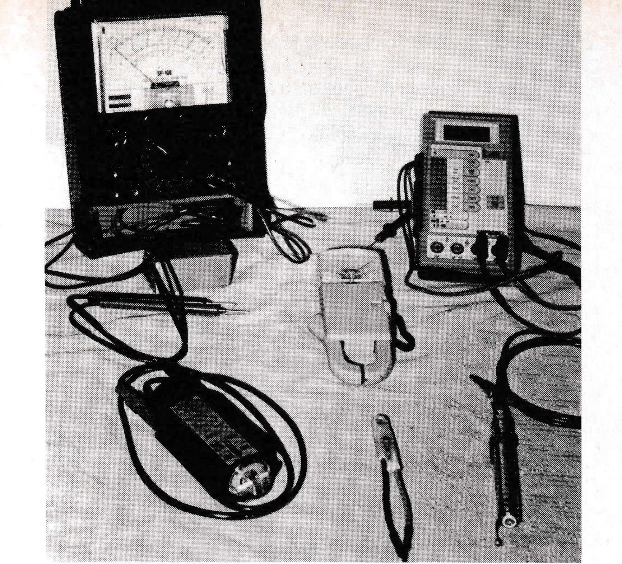
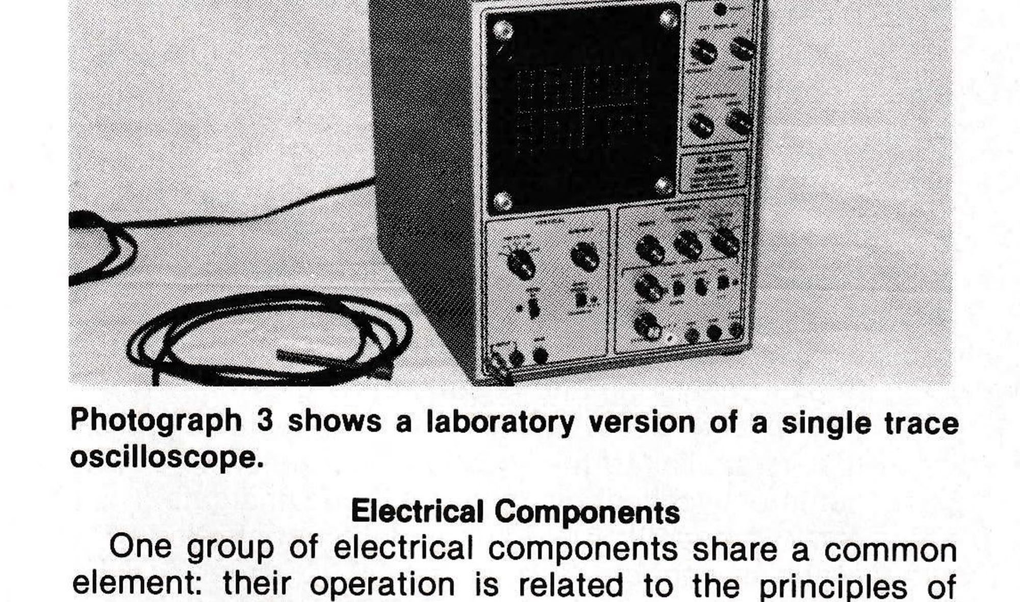
When people refer to voltages, such as 120 or 480, they are really talking about RMS voltages, and most meters (see Photograph 2) measure AC voltage and current fairly accurately, showing the results in RMS values. To see the actual waveform produced by an AC source, a sophisticated test instrument known as an oscilloscope must be used (see Photograph 3). The oscilloscope is the only instrument that will show true AC waveforms, however, due to its complexity and size, it is usually limited to laboratory and special field service use.
Electrical Components
One group of electrical components share a common element: their operation is related to the principles of magnetic inductance. An inductor is capable of storing energy in a magnetic field developed when current flows within a device such as a solenoid, relay, motor or transformer. The devices rely on the magnetic fields developed within them to operate.
A Solenoid converts electrical energy into mechanical work in the form of linear motion. This electro-mechanical device is manufactured by winding insulated wire around a hollow core. A metallic piece or “armature” is then inserted inside the core. When current is applied to the windings or “coil,” the magnetic field developed due to the current flow will cause the armature to move. The armature can only move within the core in a linear manner. The armature is usually prevented from moving too far out of the core by springs which also provide a return force.
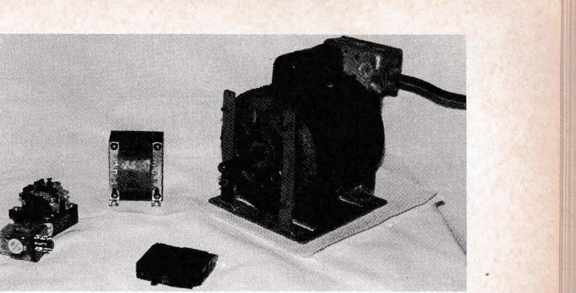
Examples of solenoid uses are brake release mechanisms, electric latches and engine starters. Solenoids are manufactured with different coils for operation on specific AC or DC voltages and provide known linear forces.
Relays are special purpose solenoids where the movable armature has been connected to a set of contacts to form an electric switch. Relays are manufactured in many switching configurations, including: single pole single throw (SPST), single pole double throw (SPDT), double pole single throw (DPST), double pole double throw (DPDT) and multipole (8P) or (4P). Relays are manufactured with either open or enclosed coils and contacts and with different coils for AC or DC operation at specific voltages which can be normally open (NO) or normally closed (NC). Some common relay uses include: telephone switching, control circuits, motor starters (Contactors), high current switching and remote switching.
Motors convert electrical energy into mechanical work in the form of rotational motion. These electro-mechanical devices are manufactured by winding insulated wire around the inside of a hollow, stationary case. Insulated wire is then wound around a piece that will become the rotating portion of the motor rotor or armature. The completed wound assembly is then held inside the stationary case with bearings. The ends of the case are capped to prevent the rotating piece from leaving it.
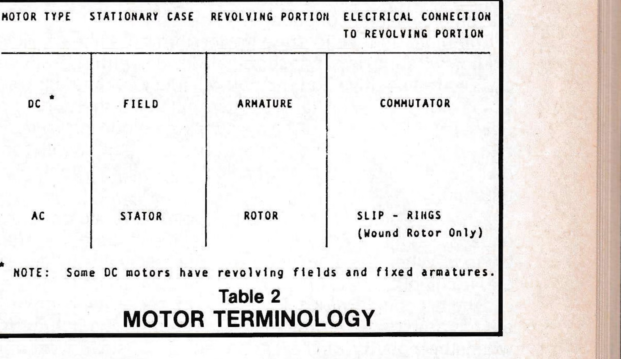
Motors can be designed to operate on AC or DC and at specific voltages. When referring to the parts of a motor, a difference exists between the terminology used to describe those that are AC and those that are DC. (See Table 2.) Motors are available in many styles, including split phase, capacitor start, “squirrel cage,” wound rotor, synchronous, series wound, shunt wound, shaded pole and salient pole.

The speed that a motor operates at can be fixed or variable. The speed of operation is dependent upon several factors, including design, applied voltage, applied frequency (AC Only), load and method of control.
The amount of useful work that a motor can produce is usually rated in horsepower (hp). Starting torque and peak hp are often stated to indicate the torque developed during starting and the intermittent maximum output of the motor.
The transformer is the only device relying on the principles of magnetic induction that does not produce motion. It also cannot be operated on Direct Current (DC), but must be operated using Alternating Current (AC) sources. The transformer is basically a device for converting voltages and currents at one level to voltages and currents at another level.
The transformer is manufactured by winding insulated wire around an iron core to form sets of windings that are electrically isolated, but share the same core. When one winding is energized, an alternating magnetic field is developed and supported by the iron core. The alternating magnetic field induces a proportional alternating voltage in the other winding. The level of the induced voltage is proportional to the applied voltage by a factor known as the wire turns ratio. The proportional voltages can be stated:
v₂ = N × v₁, where v₁ is the applied voltage, v₂ is the induced voltage and N is the ratio of turns between the windings. The current induced in the second winding is related to the current applied to the first winding: i₂ = i₁ ÷ N, where i₁ is the applied current, i₂ is the induced current and N is the ratio of turns between the windings.
Notice that the induced current is inverse to the induced voltage. In other words, if the induced voltage is higher than the applied, the induced current will be lower than the applied. This principle makes the transformer a useful device for converting low voltages to higher levels for cross-country energy transmission at lower current levels.
Transformers are manufactured in many different styles, including step-up, step-down, autotransformer, buck-boost, multi-tap, center-tap and filament. Modern transformers are among the few devices that operate at high efficiencies at about 96 to 98 percent.
Electronic Components
Modern electronic components have evolved since the late 1950’s and are currently the fastest growing area of the electrical industry. These components are known as “solid state” or semi-conductor devices.
They are called “solid state” devices because their operation relies on electron transfer through solid materials, as opposed to the emission of electrons from the hot filaments used in old-style vacuum tubes. They are often called semi-conductors because they are manufactured from materials such as silicon and germanium that are classified as semi-conductors.
The diode is a solid state device that acts like an electronic switch. It is a two-terminal device, with the anode designated positive and the cathode designated negative. When the polarity of the voltage applied to the anode is positive with respect to the cathode, the diode is “forward biased.” When the diode is “forward biased,” it will conduct and allow current to flow, just like closing a mechanical switch.
When the polarity of the voltage applied to the anode is negative with respect to the cathode, the diode is “reverse biased.” When the diode is “reverse biased,” it acts like an electronic check valve and will not allow current to flow.
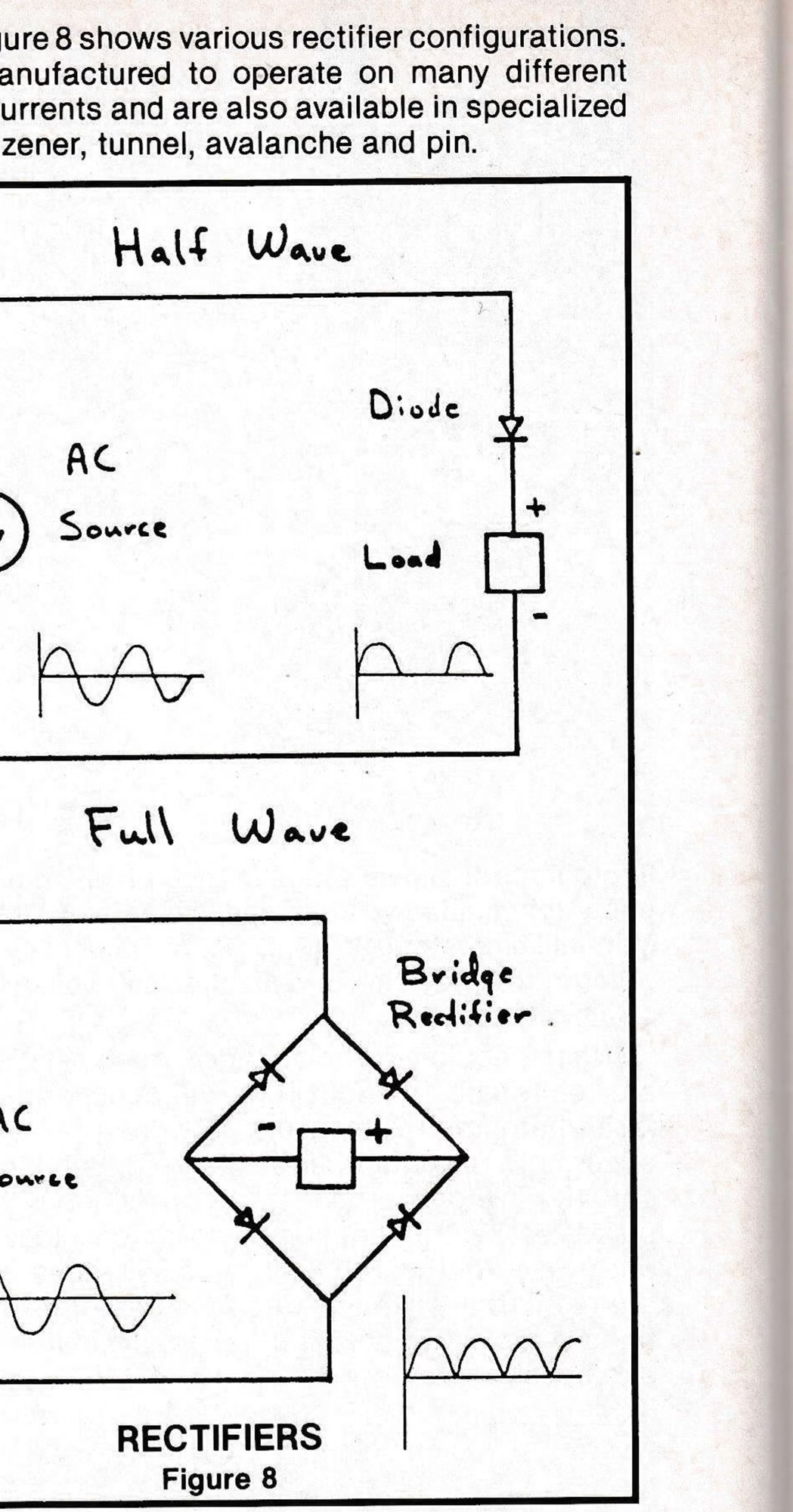
When a single diode is placed in series with an AC source and load, it will only conduct during the half cycle when the polarity of the anode will be positive. When a single diode is connected in this manner, it forms a simple “half wave” rectifier. The AC voltage applied to the diode will be converted or rectified to DC at the load.
More than one diode can be arranged to form a “full wave” rectifier that provides a DC voltage with less “ripple” to the load. Figure 8 shows various rectifier configurations. Diodes are manufactured to operate on many different voltages and currents and are also available in specialized types such as zener, tunnel, avalanche and pin.
The transistor is a solid state device that acts like a controlled electronic switch. It has three terminals commonly called the base, collector and emitter. By properly connecting the transistor with other current electronic components, a wide variety of circuits can be designed. These circuits include amplifiers, voltage regulators, computer logic, electronic ignition, television/radio equipment and monitor/control devices. This is only a sample as the actual list of all devices currently based on transistorized circuitry would be extremely long and is constantly growing.
The silicon controlled rectifier (SCR) is an electronic device that is similar to the transistor and has three terminals commonly called the anode, cathode and gate. The SCR is used in sources providing variable, controlled DC voltages and is capable of handling high current conditions, including speed controllers for DC motors.
The diode, discussed above, conducts current whenever it is “forward biased” and usually during the entire time it is “forward biased.” Furthermore, there is no easy way to vary the amount of time it will conduct when “forward biased.”
This problem is solved by using an SCR. By properly controlling the signal applied to the gate, the amount of time that the SCR conducts can be controlled. By varying the amount of time that the SCR conducts or “fires,” a variable voltage will be supplied to the load.
This is a gross oversimplification of the way an SCR circuit operates. Many complex electronic circuits are required to monitor and support the operation of typical SCR networks.
Basic Schematics
Electrical and electronic circuits can be represented either as pictorials or schematics. Pictorials are pictures or drawings that show the actual components and their locations in the circuit. Schematics are line drawings that represent the electrical connections between the symbolized components of the circuit. Schematics are developed during the design stage and are useful when trouble-shooting a circuit.
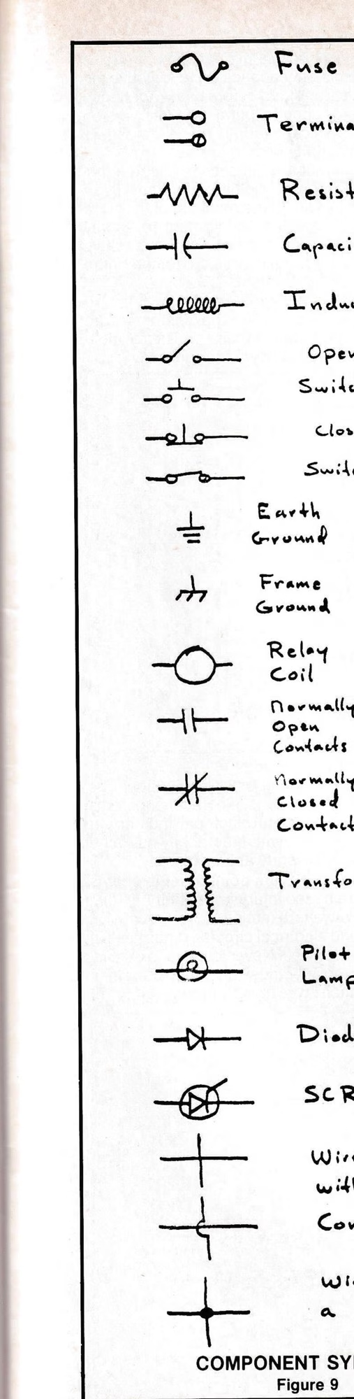
Because schematics represent the way components are actually connected, anyone trying to understand how a circuit works must be able to read them. Schematics are usually either line diagrams or block diagrams. Using the component symbols shown in Figure 9, one can create either of the basic schematics shown in Figure 10.
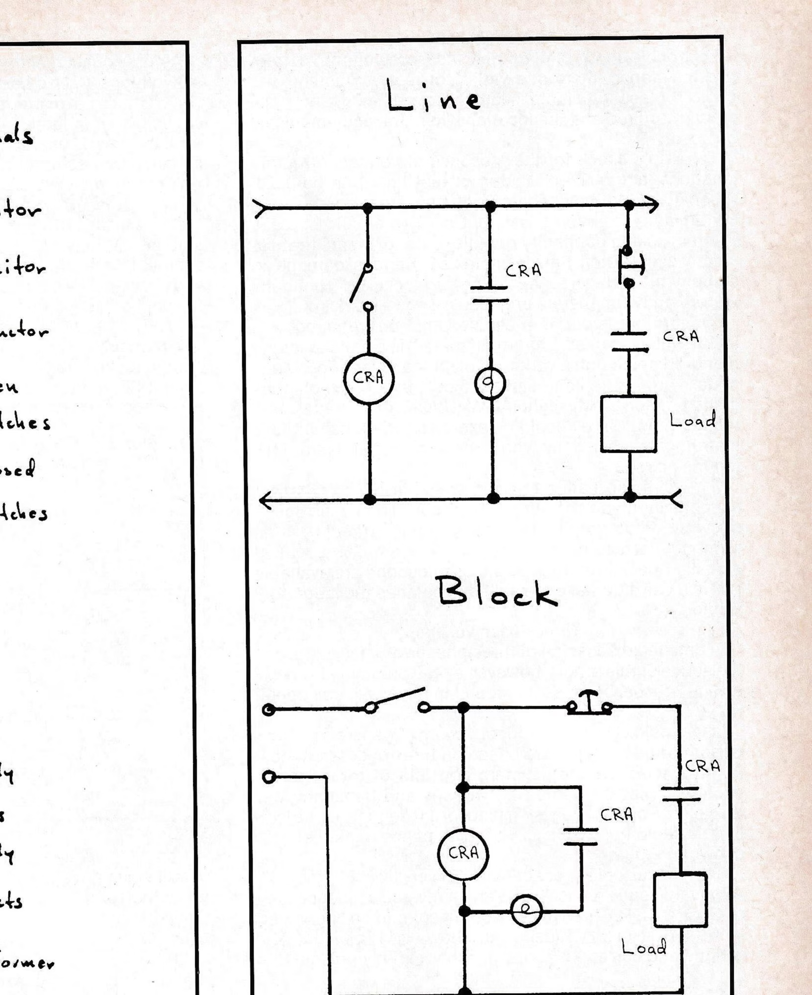
Schematics are very dependent on personal preference, because some people are more comfortable reading schematics drawn a particular way. There is nothing wrong with redrawing schematics to make them clearer so long as the circuit is properly represented.
Test Equipment
To trouble-shoot circuits and measure voltage, current and resistance, there is a variety of test equipment. The choice of test equipment is largely dependent upon the accuracy required and the location where the equipment will be used.
To simply check for the presence of voltage in remote locations, a “go-no-go” tester, or test light can be used. When checking the condition of fuses, a battery operated continuity tester works well, but caution should be used when checking continuity or resistance to ensure that circuits being tested are de-energized. Serious damage to equipment and personal injury can occur if continuity testers and ohm meters are used on energized circuits.
When more accurate measurements are required, test meters must be used. The “multi-meter” is a popular instrument for measuring a variety of electrical quantities. Multi-meters are available in several types, including volt-ohm-milliammeter (VOM), digital VOM (DVOM) and digital multimeter (DMM). Care should be exercised when using these instruments, especially when unknown quantities are being measured.
Most of these instruments are available in styles that are specifically made for rugged field use. The oscilloscope shown in Photograph 3 is a laboratory instrument that is primarily used to display and analyze complex electrical signals. Special versions of the oscilloscope are available for field use, but these are not as popular as the laboratory version.
Three-Phase Voltage
A detailed discussion of three-phase voltages is beyond the scope of this article, however, a brief summary is useful as a reference, because it is found in many ski area operations.
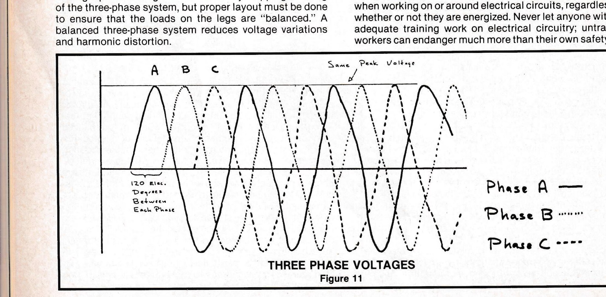
The majority of electrical energy generation and transmission systems are based on three-phase voltages. A three-phase voltage system consists of three “legs,” each one with the same RMS voltage and frequency, but the voltage on each leg is displaced 120 degrees electrically from the other two legs. The three-phase relationship is shown in Figure 11.
The phases or legs are usually labeled “A”, “B”, and “C”. A forward sequence is A, B, C and a reverse sequence is B, A, C, or A, C, B. Three-phase equipment can be connected in “Y” (wye) or “A” (delta) as shown in Figure 11. The voltage and current relationships in wye and delta circuits are complex.
Single-phase voltages are obtained by “tapping” one leg of the three-phase system, but proper layout must be done to ensure that the loads on the legs are “balanced.” A balanced three-phase system reduces voltage variations and harmonic distortion.
Power Factor
As previously mentioned, due to the complex nature of AC voltages, Ohm’s Law is only applicable to resistive circuits. Ohm’s Law must be modified before being applied to capacitive or inductive AC circuits, but a modified version of Ohm’s Law is useful when calculating Power Factor (PF), because that determines utility demand rates.
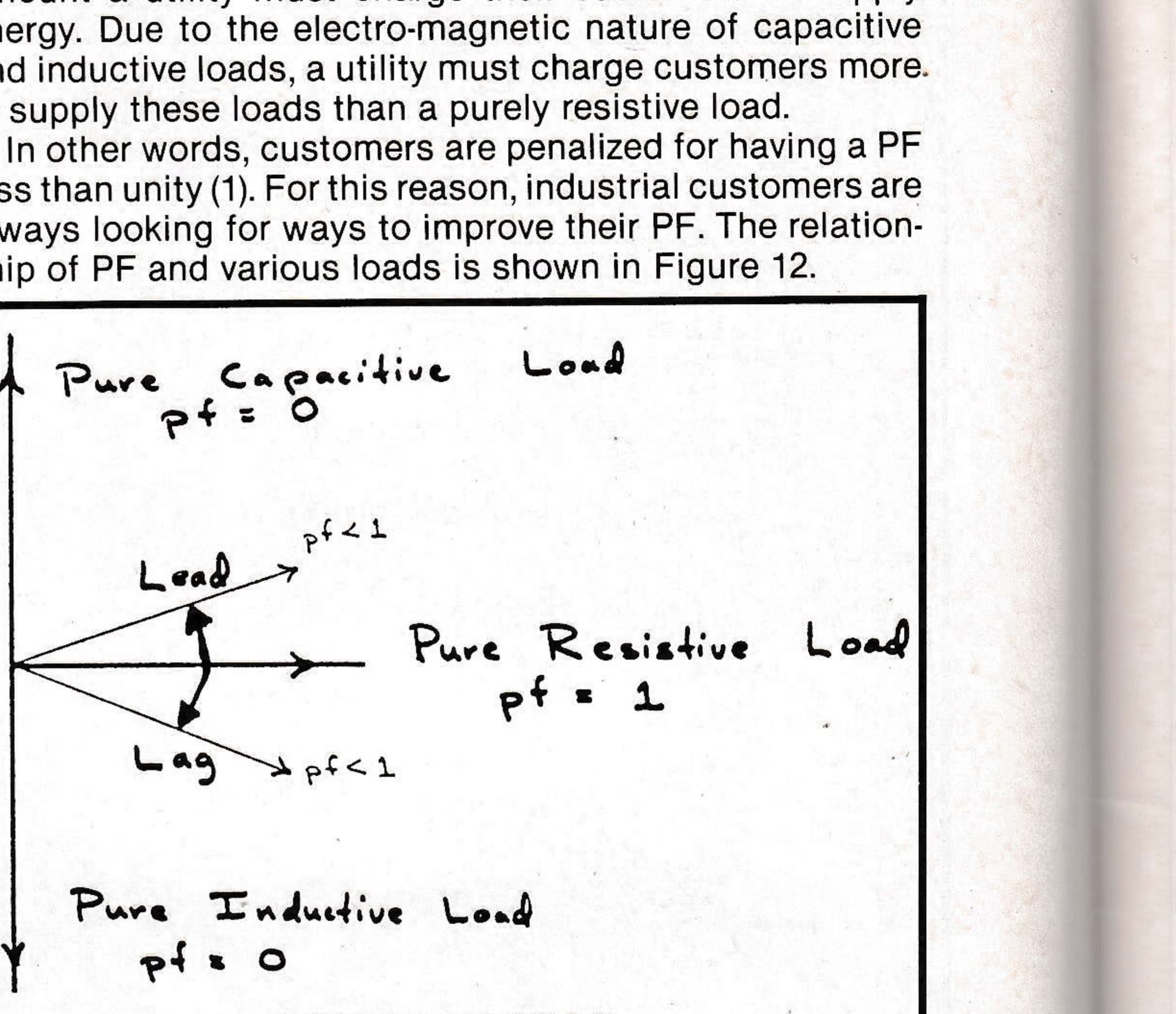
A purely resistive load, such as baseboard heat, is assigned a PF of one (1). A purely capacitive or inductive load is assigned a PF of zero (0). The PF is a measure of the extra amount a utility must charge their customers to supply energy. Due to the electro-magnetic nature of capacitive and inductive loads, a utility must charge customers more to supply these loads than a purely resistive load.
In other words, customers are penalized for having a PF less than unity (1). For this reason, industrial customers are always looking for ways to improve their PF. The relationship of PF and various loads is shown in Figure 12.
Use and Abuse
Basic knowledge, like that described above, should be useful when dealing with electricians, electrical engineers and other professionals within the electrical industry. It may also help people who work with electrically-operated equipment to use it more efficiently and effectively.
In that regard, the most important point to remember is that electrical energy can cause injury or death if handled casually or carelessly. Always exercise extreme caution when working on or around electrical circuits, regardless of whether or not they are energized. Never let anyone with inadequate training work on electrical circuitry; untrained workers can endanger much more than their own safety.