

This investigation was initiated because of the breaking of the cable of a new chairlift. The lift was a completely standard double with fixed grips. It had been erected, and was waiting for the snow.
What came was not the snow, but fog and wind; and two days later, when the fog was gone, the chairlift was lying on the ground, the cable broken near the top terminal.
The suspicion was sabotage. The lift builder, Mr. Doppelmayr, asked me to carry out the investigation. I found the saboteur after a short time: it was the wind. Mr. Doppelmayr said he had difficulty imagining this, and he asked me to make a fundamental study about the behavior of chairs under the influence of wind. So, we can thank Mr. Doppelmayr: firstly, for having ordered the investigation, which was not inexpensive; and secondly, for having agreed to publish the results.
Wind tunnel tests
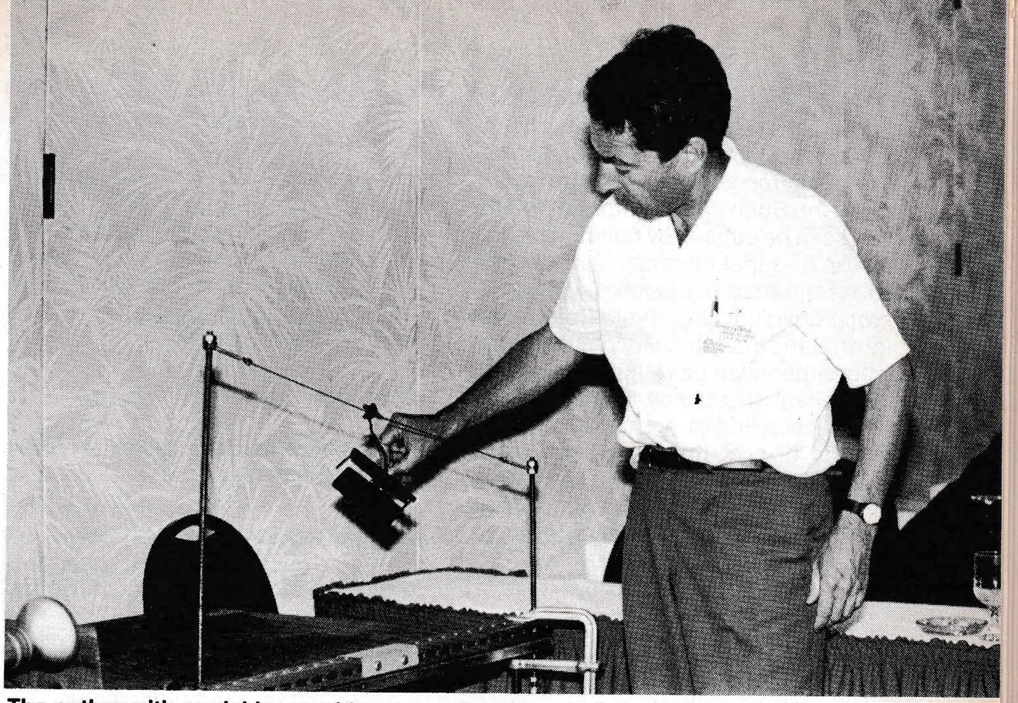
Extensive tests were conducted in a wind tunnel. We learned the following:
1. If the wind is coming from the front in a uniform way, the chair will be deflected in direct proportion to the increase in total pressure. The surprising thing is that the deflection depends only in a small way on the performance of the chair. A chair with lattice design suffers nearly the same deflection as one with solid walls.
We can explain this in the following way: the wind force acting on the backrest pushes the chair upwards, and the wind force acting on the seat has a downwards component. Therefore, these two forces work in opposite directions. The difference between these two forces affects the deflection of the chair, and this difference depends but little on the performance of the chair. Consequently, the deflection of the chair is greatest if the seat is in an upright position, and it is lowest if the backrest is depressed.
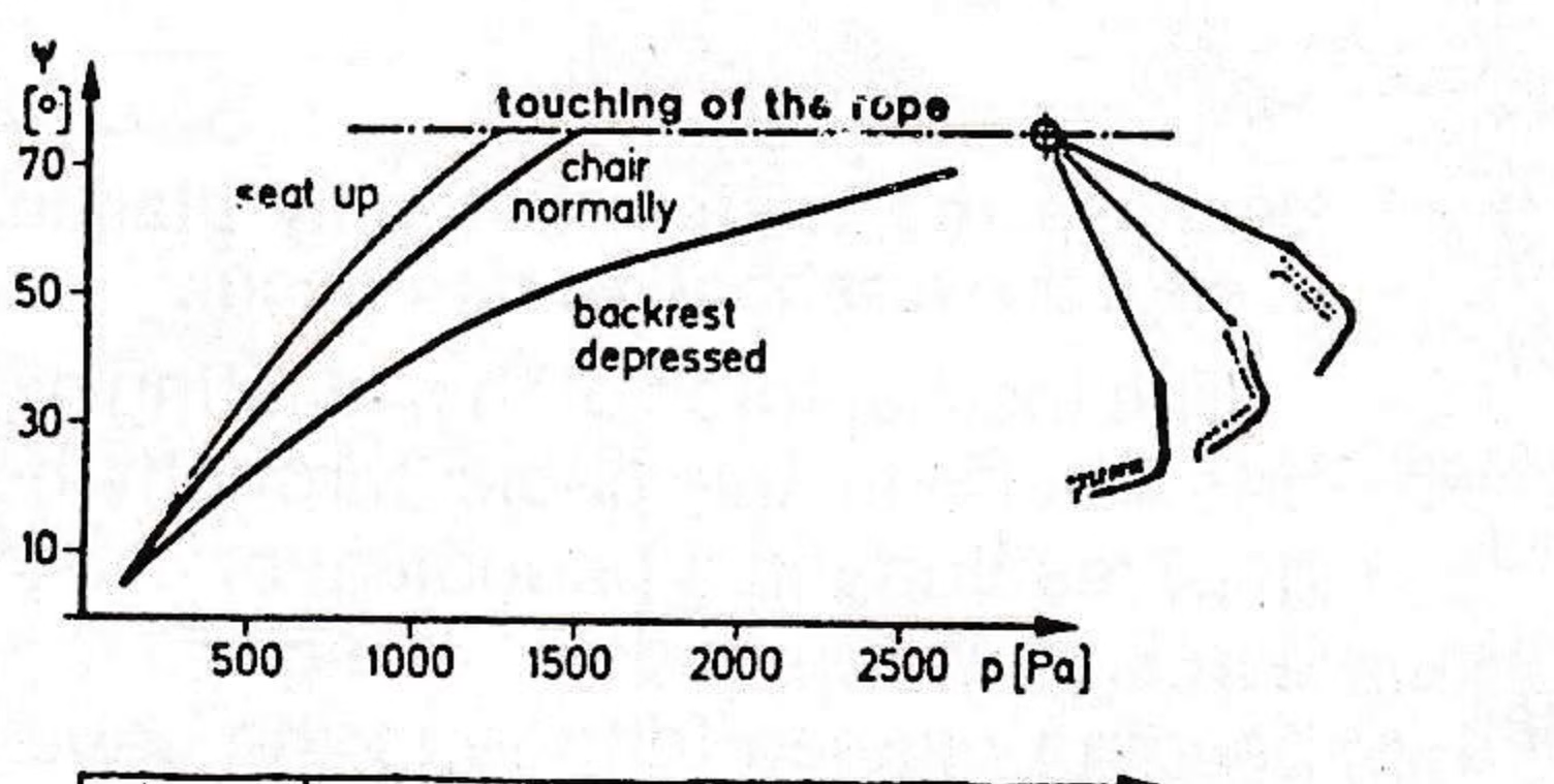
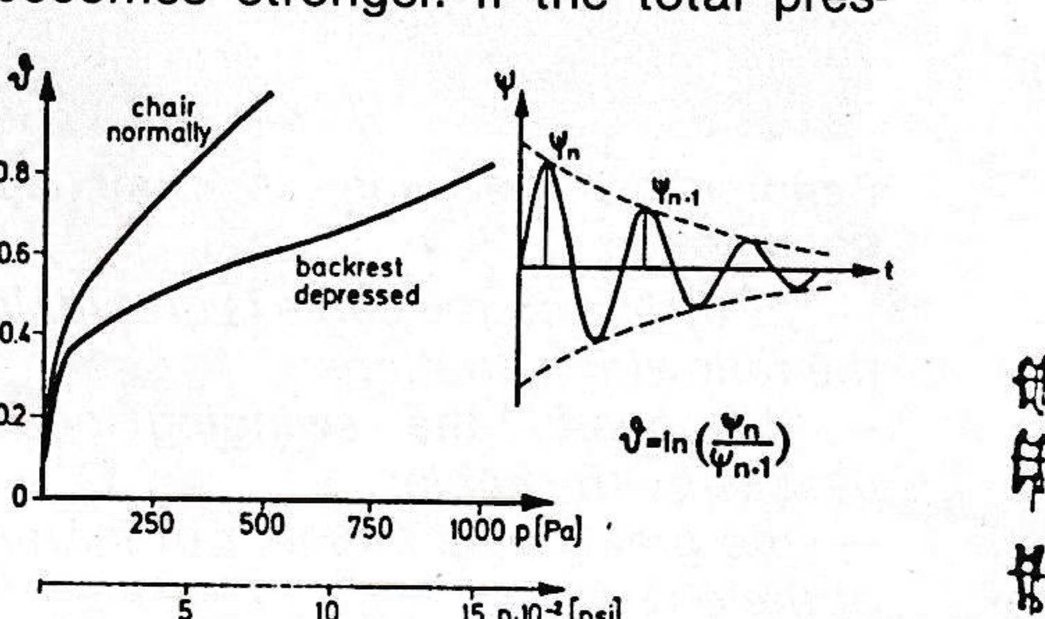
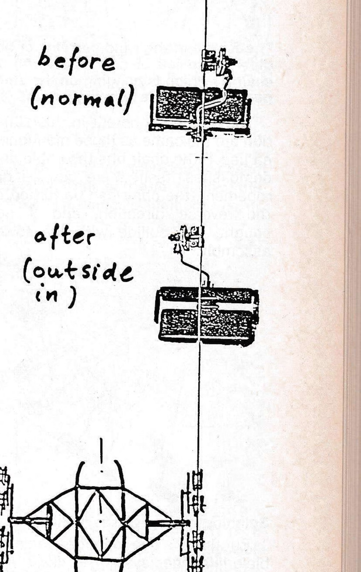
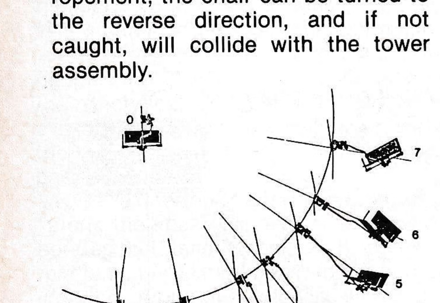
Another observation is that the chair stays in this deflected position in a stable way, meaning that the swinging dampens itself. This happens as quickly as the total pressure becomes stronger. If the total pressure rises even more, the chair will go still higher until it is held back by the rope. In this case the chair will flutter around the rope, with three possible consequences: 1) damage to the chair; 2) a possible deropement if the blow is strong enough; and 3) a turning of the chair in the opposite direction. (Ed. note: when this occurs the grip ends up upside down.) In this case the grip is switched to the inside of the cable, with the consequence that, when the lift is started, the chair hanger will collide with the crossarm and other sheave assembly components at the tower.
If the wind does not come from the front, but is still uniform, the behavior of the chair does not change fundamentally, except for the fact that there is now also a deflection to the side.
If the wind is not uniform, the behavior of the chair is fundamentally different. Such a non-uniformity of the wind can be caused by buildings (such as top terminal lift shacks) as well as by terrain features (such as rock outcroppings and cliffs). A sheltered zone is created behind such obstacles where there will be reduced pressure, and where there may be no wind or even back wind. If a chair is stopped so that it is at the border of one of these sheltered zones and the windy area, the chair begins to spin around like a top. This can happen even at moderate wind speeds.
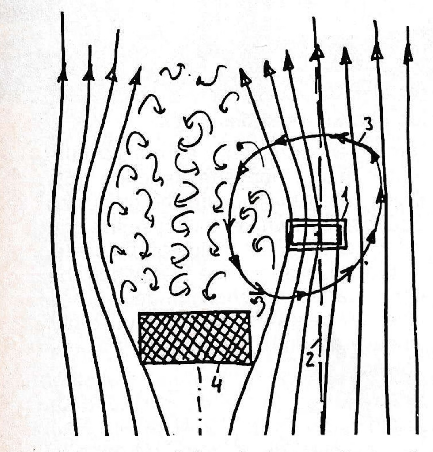
The dangers inherent in this situation are the same as those mentioned earlier: 1) the chair hits the cable and demolishes itself; there can be deropement; the chair can be turned to the reverse direction, and if not caught, will collide with the tower assembly.
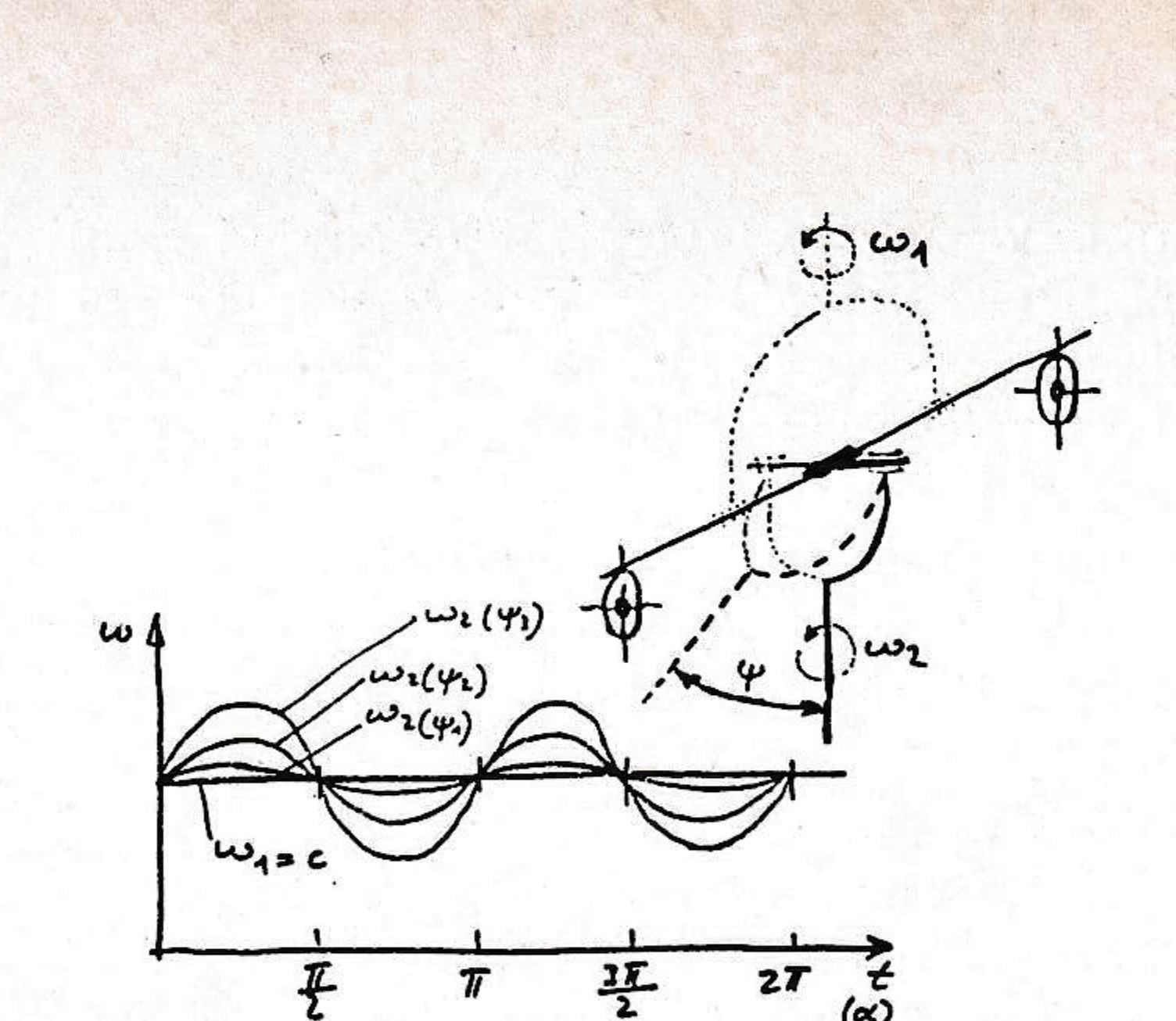
But there is one more danger: a cable/grip/hanger system is like a universal joint, and it is well known that a universal joint does not translate the rotation in a uniform way. A periodical swing is superimposed on the rotation. This superimposed swing is greater as a function of the increase in declination Y of the universal joint. In our case, there is no rotation of the primary part of the universal joint (ψ₁ = 0), but there is a continuous changing of the direction and the size of the declination of the secondary part. This secondary part is the chair. Therefore, if the chair spins around, there is also a periodical twisting of the chair.
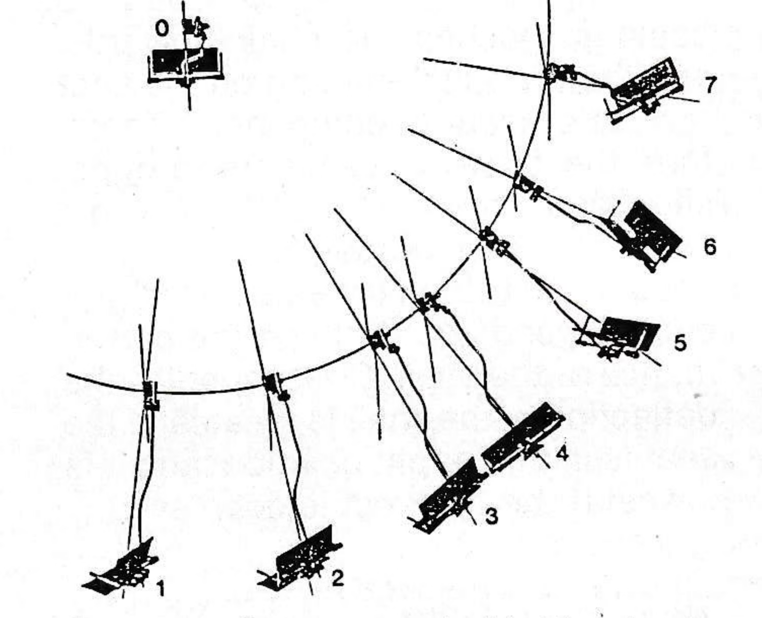
The inertial force of this twisting exerts itself on the cable through the grip, resulting in a periodical or cyclic bending at the ends of the grip. This bending causes fatigue in the cable, which can result in broken wires and possible cable breakage.
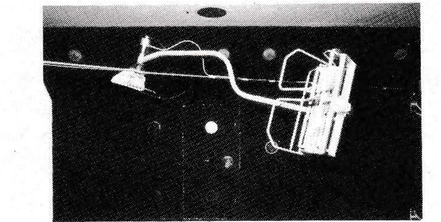
The stress on the cable is greater in the following situations:
- the nearer the swinging chair passes by the cable;
- the greater the moment of inertia of the chair;
- the shorter the contact between grip and cable;
- the less the cable tension.
Effect on the cable
In order to find out how long a cable can resist such repeated bending, tests have been carried out in the laboratory. We wanted to duplicate as best we could the conditions mentioned at the beginning. We therefore tensioned a similar piece of cable with the same force and fixed it to a grip of the same type. This grip was then twisted back and forth until the cable broke.
The amount of the torque on the grip at the accident can only approximately be determined by examining the deformation, or bending, that occurred.
The deformation of the grip begins when its declination is 37°, and reaches the level of the accident at 43°. We accordingly carried out two tests:
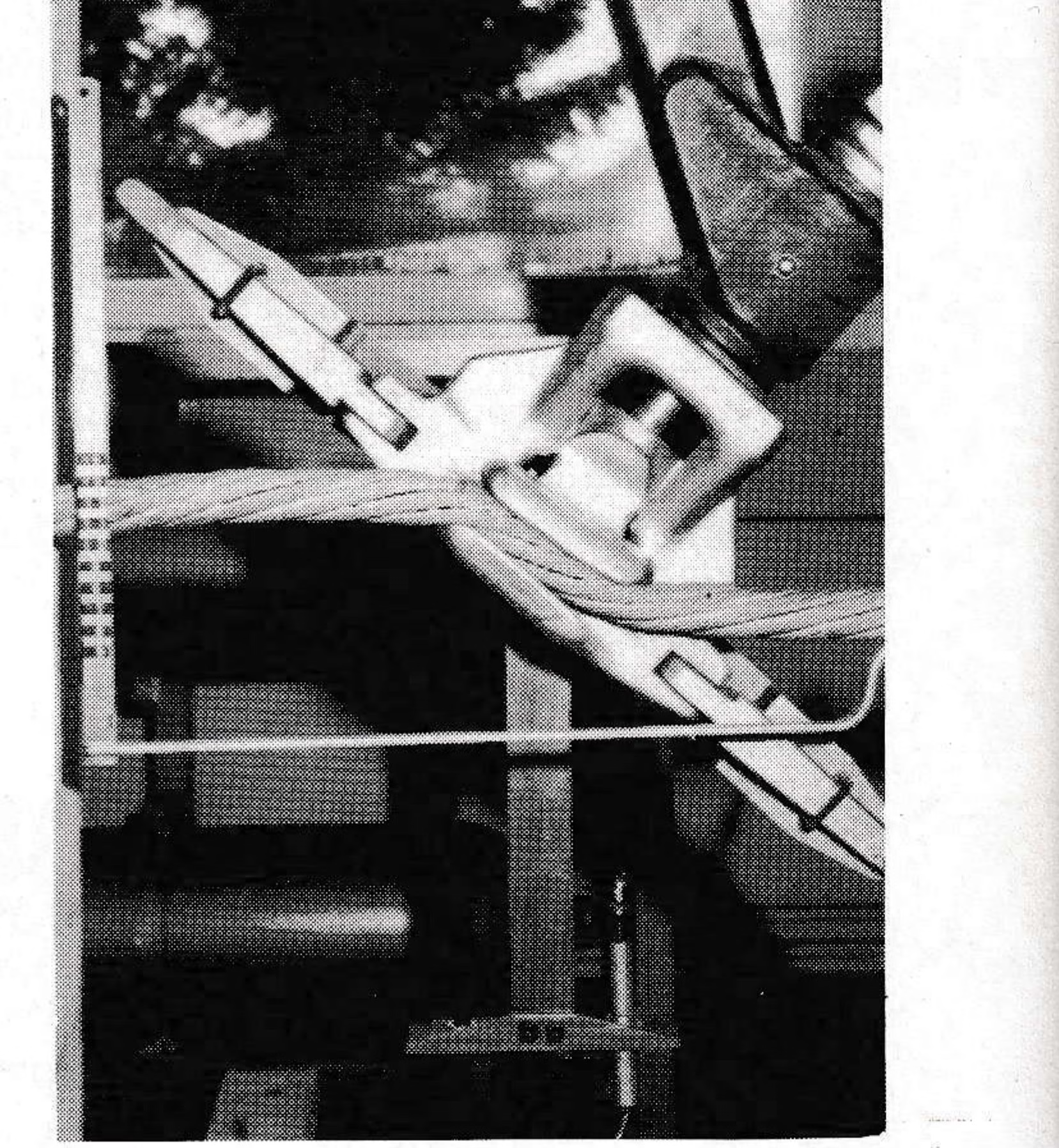
1) Declination 0–43° (the minimum reached on the occasion of the accident): the cable broke after approximately 5,000 repeated bendings;
2) Declination −37° to +43° (the maximum reached on the occasion of the accident): the cable broke after approximately 500 repeated bendings.
Recommendations
Based on these facts, some recommendations can be made. The following list is not complete, and it is certainly possible to find additional. It is also obvious that not all of these recommendations can easily be exercised. But this is not necessary. It is enough to find just one effective procedure that will:
- prevent the cause of the swinging;
- interrupt the uniform repetitive swinging (change the harmonics of the motion);
- dampen the swing.
The practical application must be selected based on the local conditions. Recommendations for project engineers:

1) Avoid areas exposed to wind (ridges, crests); 2) For steep chairlifts, wind from above is especially critical; 3) Avoid the boundary areas between windy and sheltered zones; 4) Garage the chairs.
Recommendations for designing engineers:
1) Design foldable backrests for the chairs; 2) Dampen the chair swing — in a degressive way, meaning that the dampening effect must not be working if the chair is declined all the way to the proximity of the rope.
3) Design long grips — i.e. that part of the grip that is in contact with the cable; 4) Choose a higher tension for the cable; 5) Select higher sheave loadings; 6) Use lattice rather than tubular towers.
Recommendations for area management:
1) Reduce the sharpness of the border zones between windy sections and sheltered sections behind barriers — natural or man-made; 2) Do not stop chairs in these border zones; 3)Do not stop chairs behind a tower; 4) Tie the bottoms of a critical cluster of chairs together when stopping the lift.
5) After a heavy wind, make sure no chairs are reversed before starting up; 6) Following protracted periods of wind, check the condition of the cable at the ends of grips.
Conclusion
This study should not have taken away your enthusiasm for building and operating chairlifts. To the contrary: you can do so with confidence because you now know what to do to avoid these problems. I am therefore confident that I shall never again get the opportunity to investigate the wind!
The Institute of Lightweight Structures and Ropeways
*The author of the accompanying article, Prof. Dr. Gabor Oplatka, heads the Ropeways Section of this Institute, and as such is one of the world’s leading authorities on transportation by wire rope. SAM asked him to describe the functioning of this Institute, since there is nothing quite like it in the U.S.*
The Institute of Lightweight Structures and Ropeways forms a part of the Swiss Federal Institute of Technology in Zurich (ETH), which has over a 125-year tradition, its lectures being attended by about 8,000 students. Intensive research work with regard to ropeways was started during the late 1950’s under the direction of Prof. O. Zweifel. The institute is now directed by Prof. Dr. H.-R. Meyer-Piening.
Activities
The institute’s activities fall into three spheres: instruction, research and services. For the Ropeways Section, instruction means giving lectures and field work for engineering students — civil and mechanical — as well as engineering in land improvement, water management and surveying. Courses are also given for the technical staffs of ropeway enterprises.
The research work addresses problems involving:
- Cables (investigation of the different parameters influencing the life expectancies of cables and connections);
- Friction problems (drive, brakes, especially track-rope brakes);
- Oscillation problems (dynamic performance of the ropeways, frictional oscillations, etc.)
- Lightweight structures (cabins, attachment);
- Testing methodology and instrumentation development.
Research projects are prioritized, with questions of mainly commercial interest being treated when there is available capacity — unless the customer is willing to cover the total expense.
The research is financially supported by a working group consisting of the Swiss Supervising Authorities, the rope manufacturers, the principal lift manufacturers, as well as the Union of Ropeway Enterprises — in addition to the Institute itself. It is also assisted by a contribution from the national research fund. Results are reviewed by the working group, and usually published.
Services
These include:
- Consultations with authorities, as well as with ropeway enterprises;
- Expert witnessing in disputes and accident investigations (whenever possible, given in a neutral way, that is, not on behalf of a certain party, but only by agreement with both parties or by court order);
- Maintaining a technical library.
A Sampling of Institute Activities